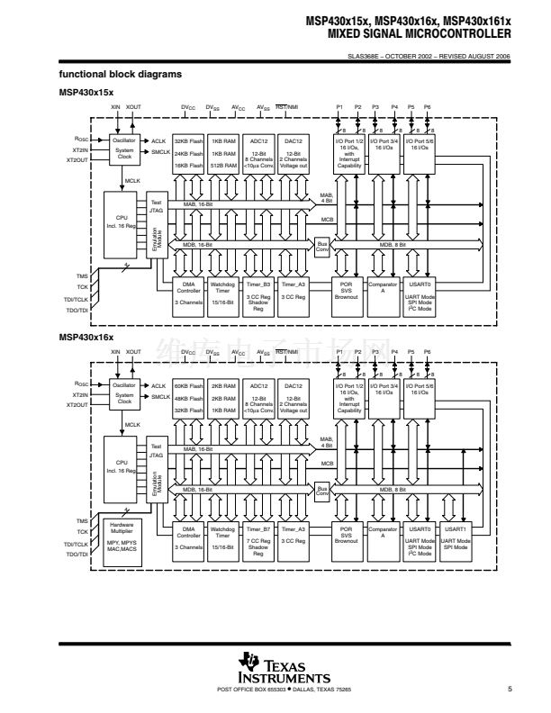
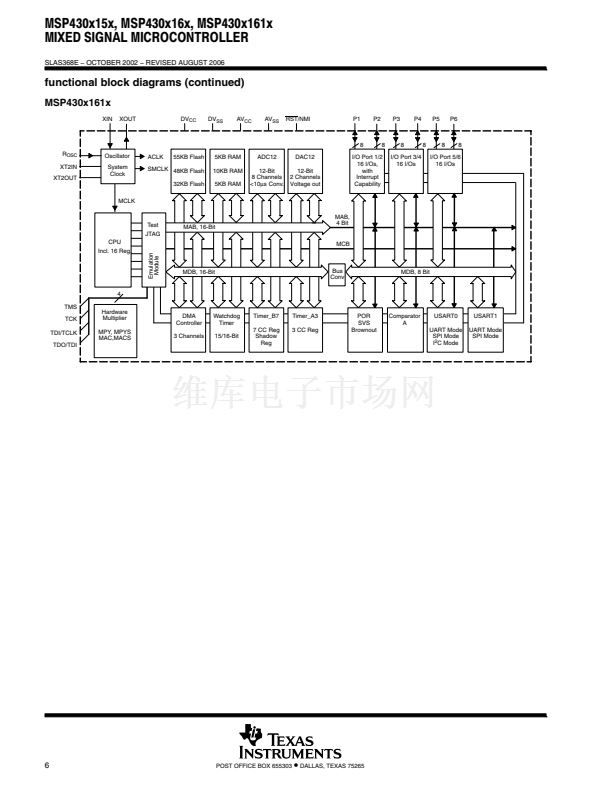
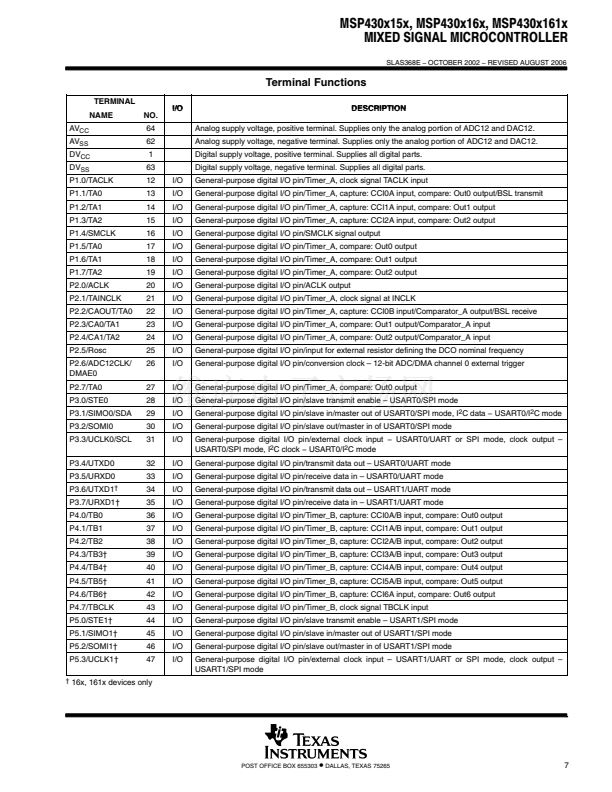
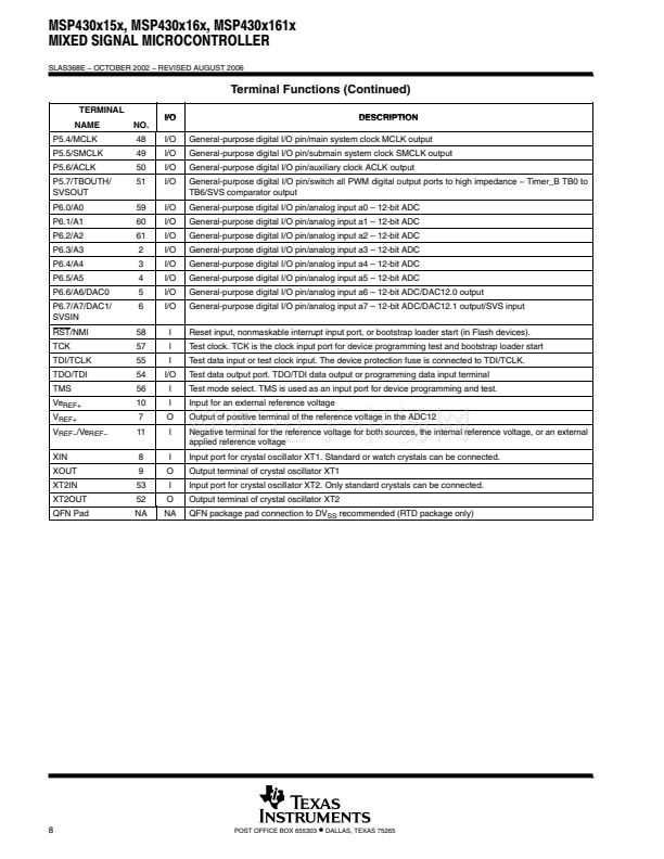
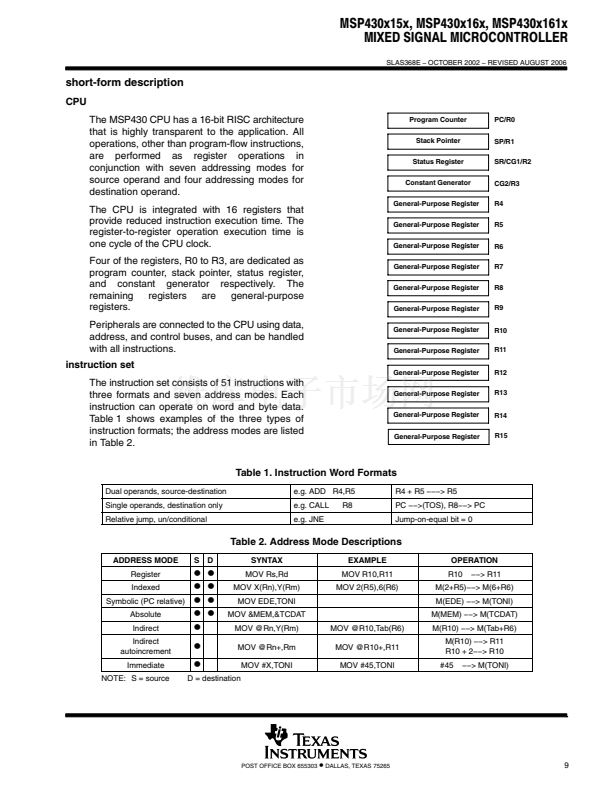
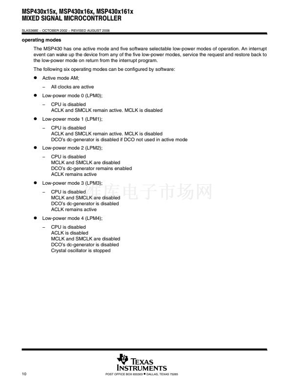
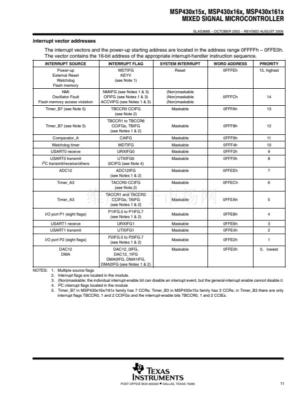
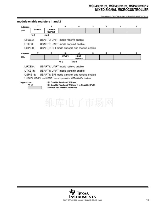
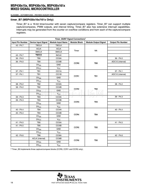
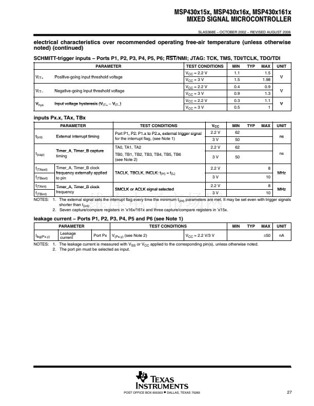
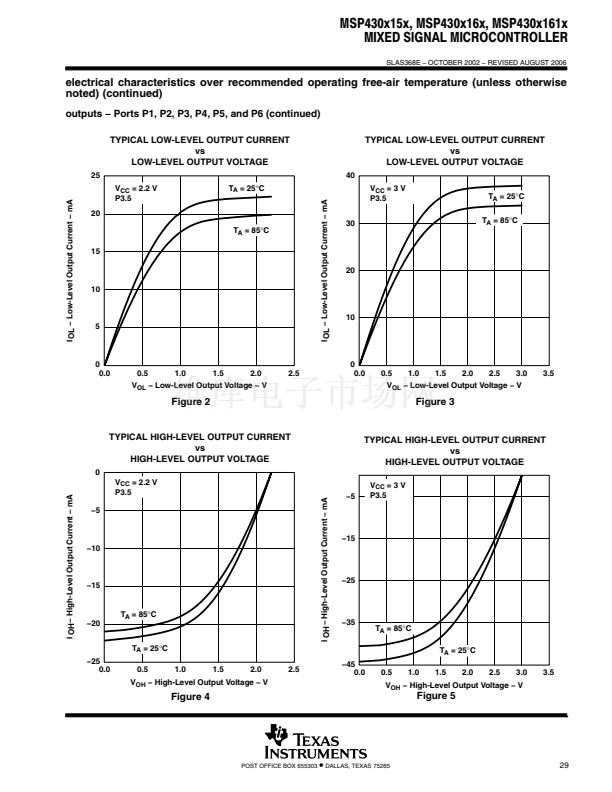
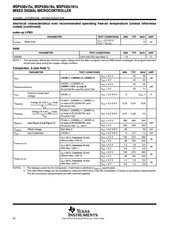
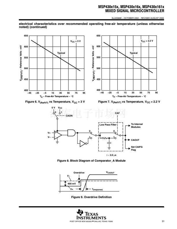
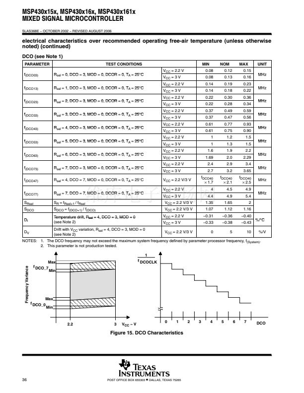
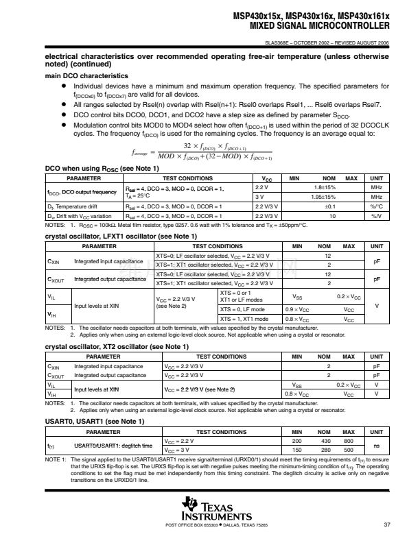
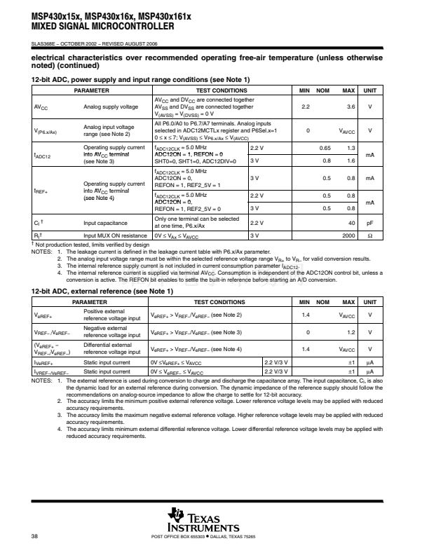
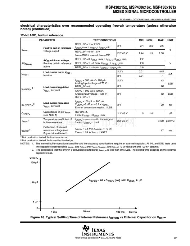
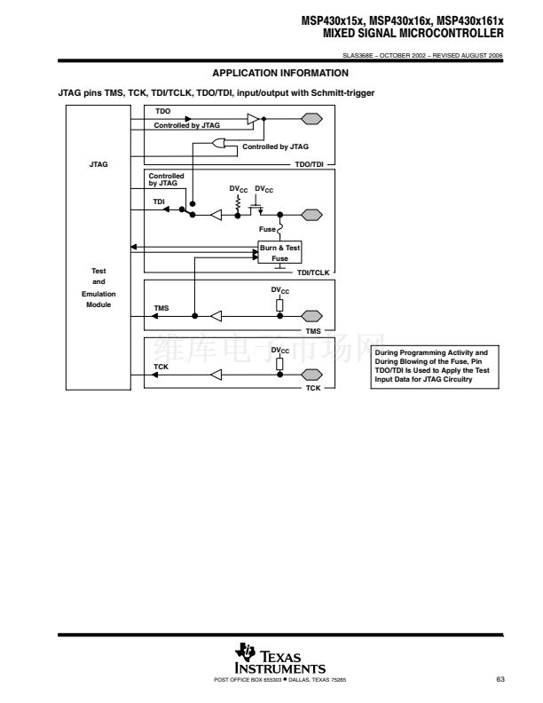
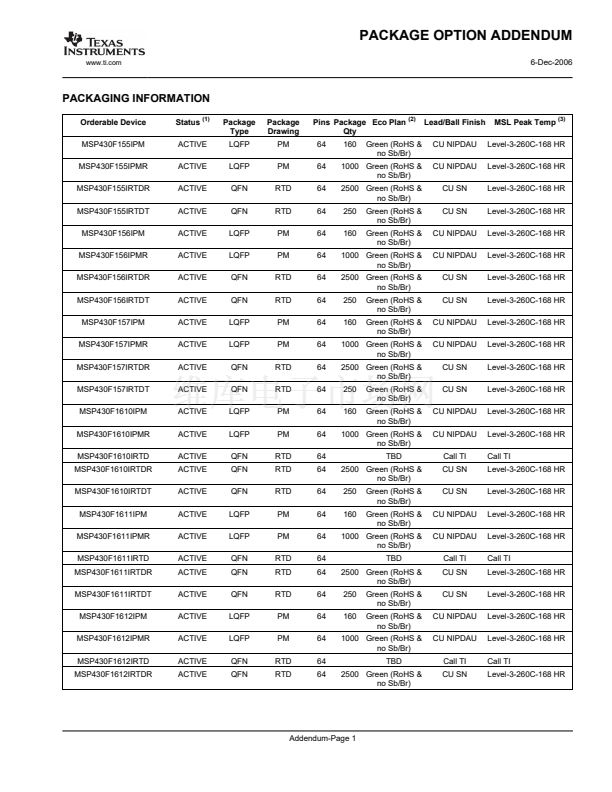
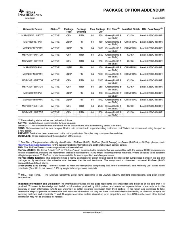
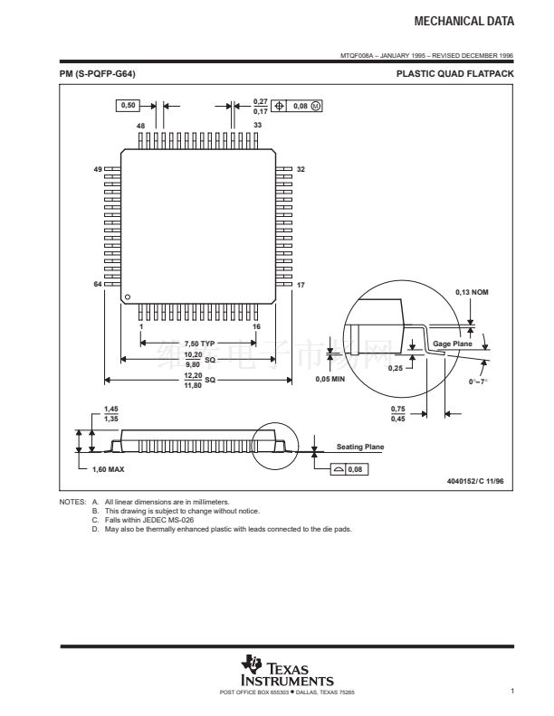
MSP430x15x, MSP430x16x, MSP430x161x
MIXED SIGNAL MICROCONTROLLER
SLAS368E 鈭?OCTOBER 2002 鈭?REVISED AUGUST 2006
electrical characteristics over recommended operating free-air temperature (unless otherwise
noted) (continued)
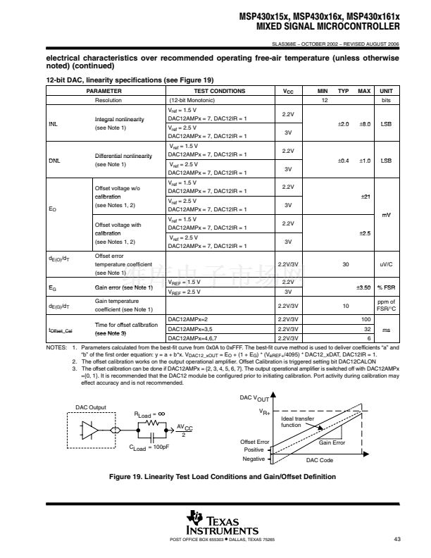
12-bit DAC, linearity specifications (see Figure 19)
PARAMETER
Resolution
Integral nonlinearity
(see Note 1)
TEST CONDITIONS
(12-bit Monotonic)
V
ref
= 1.5 V
DAC12AMPx = 7, DAC12IR = 1
V
ref
= 2.5 V
DAC12AMPx = 7, DAC12IR = 1
V
ref
= 1.5 V
DAC12AMPx = 7, DAC12IR = 1
V
ref
= 2.5 V
DAC12AMPx = 7, DAC12IR = 1
V
ref
= 1.5 V
DAC12AMPx = 7, DAC12IR = 1
V
ref
= 2.5 V
DAC12AMPx = 7, DAC12IR = 1
V
ref
= 1.5 V
DAC12AMPx = 7, DAC12IR = 1
V
ref
= 2.5 V
DAC12AMPx = 7, DAC12IR = 1
2.2V
卤2.0
卤2
0
3V
2.2V
卤0.4
卤0
4
3V
2.2V
卤21
3V
mV
2.2V
卤2.5
卤2
5
3V
卤1
0
卤1.0
LSB
卤8
0
卤8.0
LSB
V
CC
MIN
12
TYP
MAX
UNIT
bits
INL
DNL
Differential nonlinearity
(see Note 1)
E
O
Offset voltage w/o
calibration
(see Notes 1, 2)
Offset voltage with
calibration
(see Notes 1, 2)
d
E(O)
/d
T
Offset error
temperature coefficient
(see Note 1)
Gain error (see Note 1)
Gain temperature
coefficient (see Note 1)
2.2V/3V
V
REF
= 1.5 V
V
REF
= 2.5 V
2.2V
3V
2.2V/3V
DAC12AMPx=2
2.2V/3V
2.2V/3V
2.2V/3V
30
uV/C
E
G
d
E(G)
/d
T
卤3.50
卤3
50
10
100
32
6
% FSR
ppm of
FSR/掳C
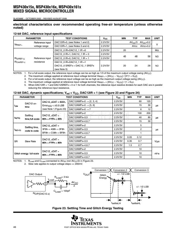
t
Offset_Cal
Time for offset calibration
(see Note 3)
DAC12AMPx=3,5
DAC12AMPx=4,6,7
ms
NOTES: 1. Parameters calculated from the best-fit curve from 0x0A to 0xFFF. The best-fit curve method is used to deliver coefficients 鈥渁鈥?and
鈥渂鈥?of the first order equation: y = a + b*x. V
DAC12_xOUT
= E
O
+ (1 + E
G
) * (V
eREF+
/4095) * DAC12_xDAT, DAC12IR = 1.
2. The offset calibration works on the output operational amplifier. Offset Calibration is triggered setting bit DAC12CALON
3. The offset calibration can be done if DAC12AMPx = {2, 3, 4, 5, 6, 7}. The output operational amplifier is switched off with DAC12AMPx
={0, 1}. It is recommended that the DAC12 module be configured prior to initiating calibration. Port activity during calibration may
effect accuracy and is not recommended.
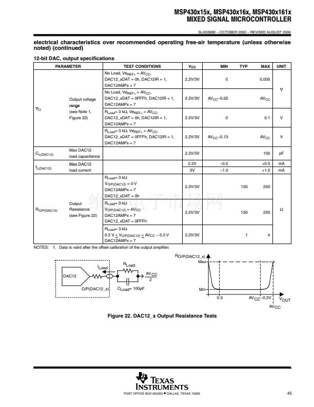
DAC V OUT
DAC Output
RLoad =
AV CC
2
CLoad = 100pF
Offset Error
Positive
Negative
Gain Error
DAC Code
VR+
Ideal transfer
function
Figure 19. Linearity Test Load Conditions and Gain/Offset Definition
POST OFFICE BOX 655303
鈥?/div>
DALLAS, TEXAS 75265
43


 1
1
 2
2
 3
3
 4
4
 5
5
 6
6
 7
7
 8
8
 9
9
 10
10
 11
11
 12
12
 13
13
 14
14
 15
15
 16
16
 17
17
 18
18
 19
19
 20
20
 21
21
 22
22
 23
23
 24
24
 25
25
 26
26
 27
27
 28
28
 29
29
 30
30
 31
31
 32
32
 33
33
 34
34
 35
35
 36
36
 37
37
 38
38
 39
39
 40
40
 41
41
 42
42
 43
43
 44
44
 45
45
 46
46
 47
47
 48
48
 49
49
 50
50
 51
51
 52
52
 53
53
 54
54
 55
55
 56
56
 57
57
 58
58
 59
59
 60
60
 61
61
 62
62
 63
63
 64
64
 65
65
 66
66
 67
67
 68
68
 69
69
 70
70
 71
71
 72
72
 73
73
