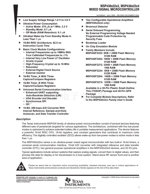
MSP430x22x2, MSP430x22x4
MIXED SIGNAL MICROCONTROLLER
SLAS504A 鈭?JULY 2006 鈭?REVISED DECEMBER 2006
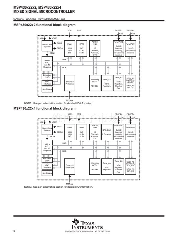
peripherals
Peripherals are connected to the CPU through data, address, and control busses and can be handled using
all instructions. For complete module descriptions, refer to the
MSP430x2xx Family User鈥檚 Guide.
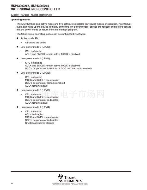
oscillator and system clock
The clock system is supported by the basic clock module that includes support for a 32768-Hz watch crystal
oscillator, an internal very low power, low frequency oscillator, an internal digitally-controlled oscillator (DCO),
and a high frequency crystal oscillator. The basic clock module is designed to meet the requirements of both
low system cost and low power consumption. The internal DCO provides a fast turn-on clock source and
stabilizes in less than 1
碌s.
The basic clock module provides the following clock signals:
D
Auxiliary clock (ACLK), sourced from a 32768-Hz watch crystal, a high frequency crystal, or the internal very
D
D
low power LF oscillator.
Main clock (MCLK), the system clock used by the CPU.
Sub-Main clock (SMCLK), the sub-system clock used by the peripheral modules.
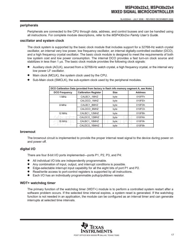
DCO Calibration Data (provided from factory in flash info memory segment A, see Note)
DCO Frequency
1 MHz
8 MHz
12 MHz
16 MHz
Calibration Register
CALBC1_1MHZ
CALDCO_1MHZ
CALBC1_8MHZ
CALDCO_8MHZ
CALBC1_12MHZ
CALDCO_12MHZ
CALBC1_16MHZ
CALDCO_16MHZ
Size
byte
byte
byte
byte
byte
byte
byte
byte
Address
010FFh
010FEh
010FDh
010FCh
010FBh
010FAh
010F9h
010F8h
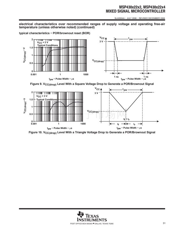
brownout
The brownout circuit is implemented to provide the proper internal reset signal to the device during power on
and power off.
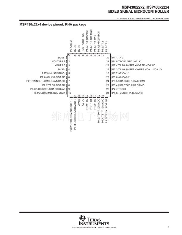
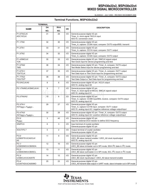
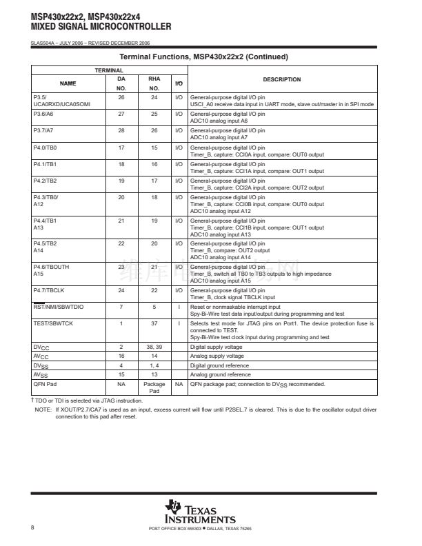
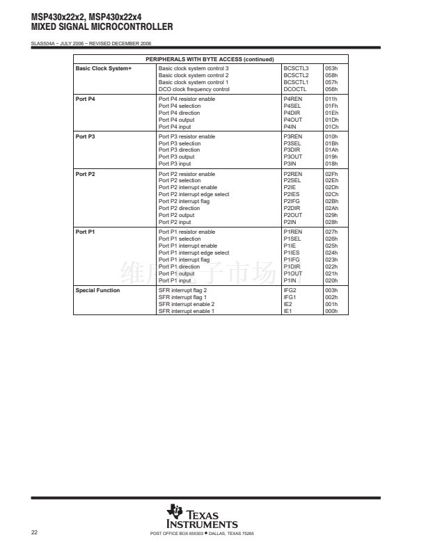
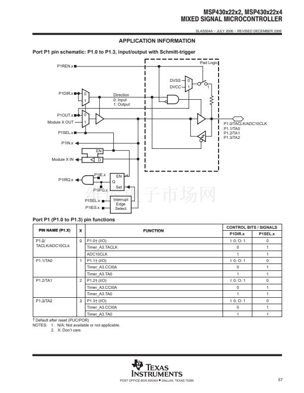
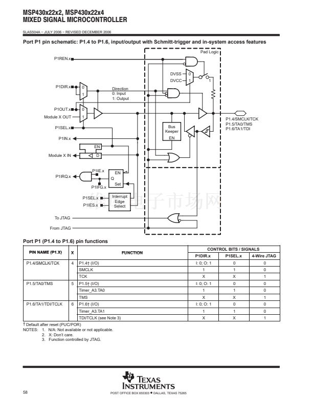
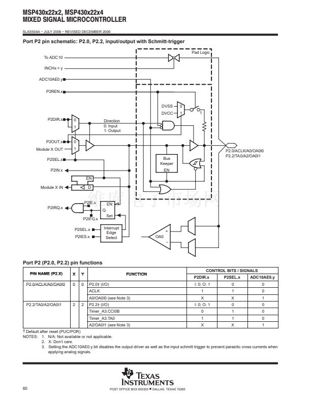
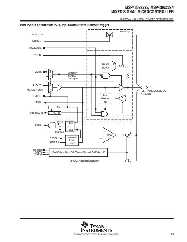
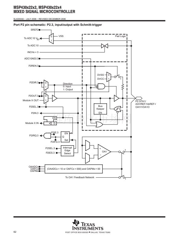
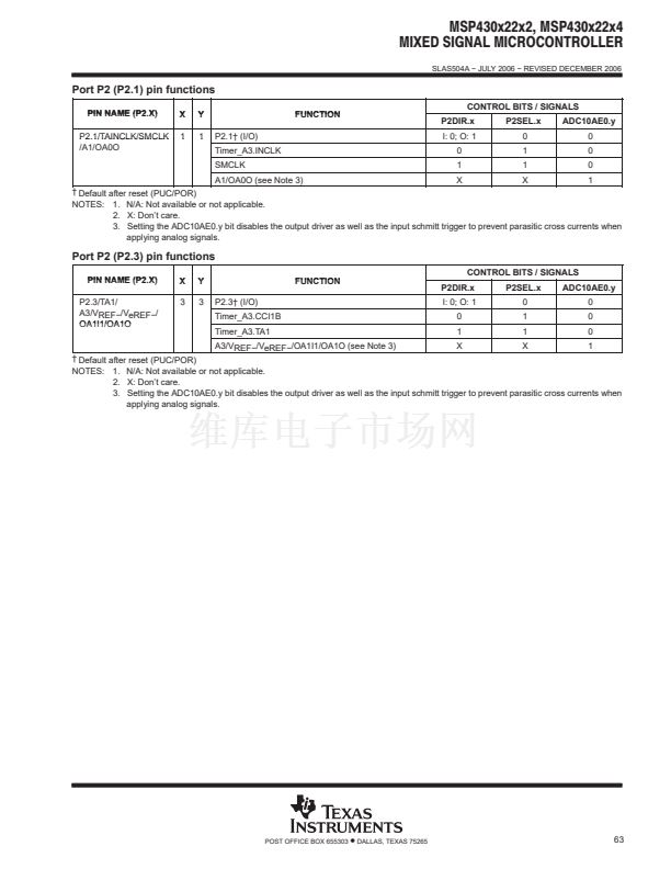
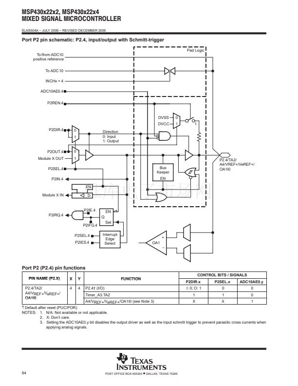
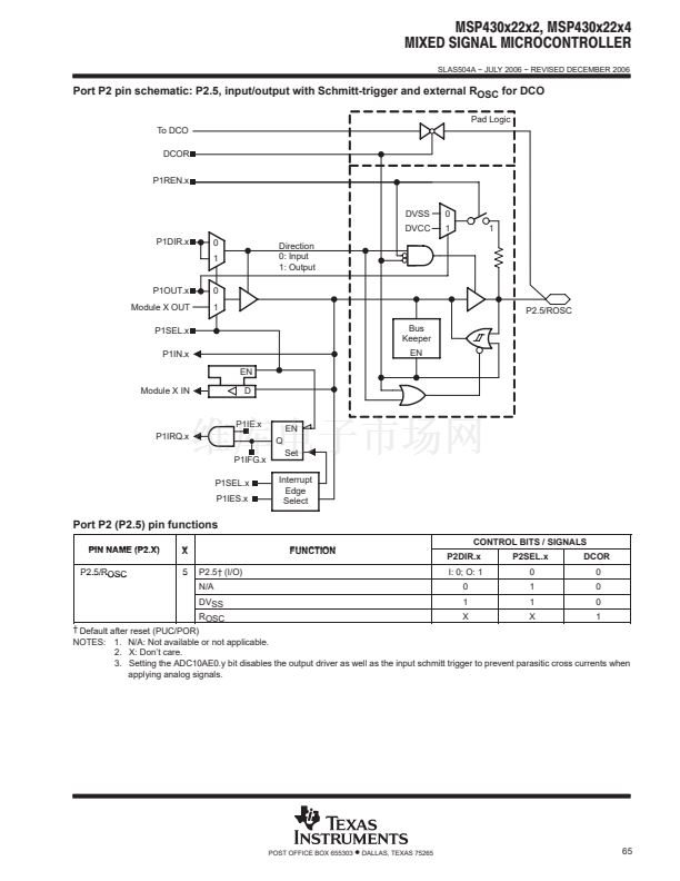
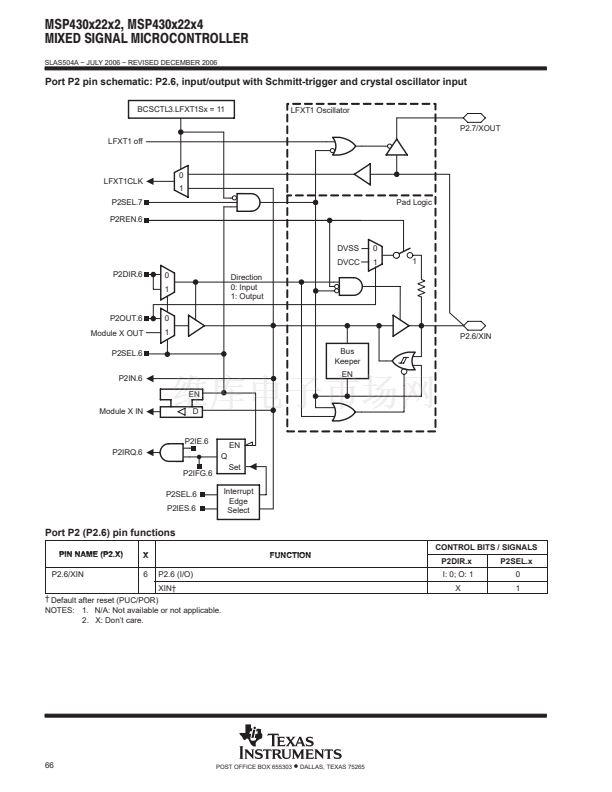
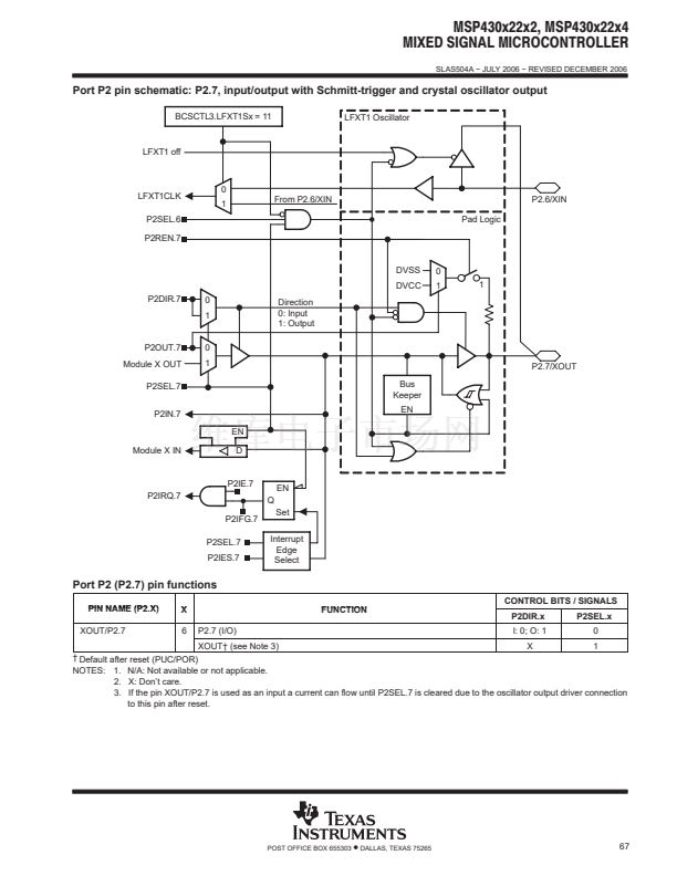
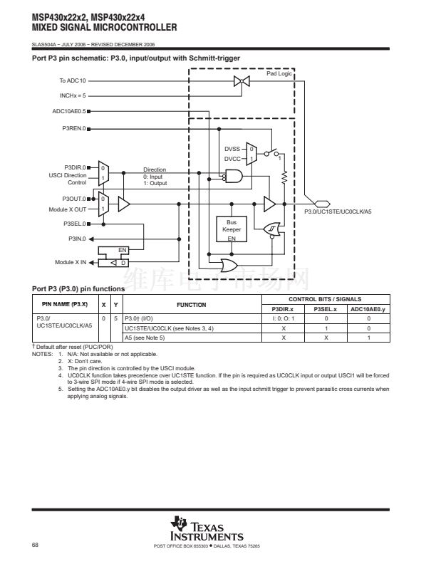
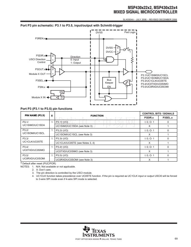
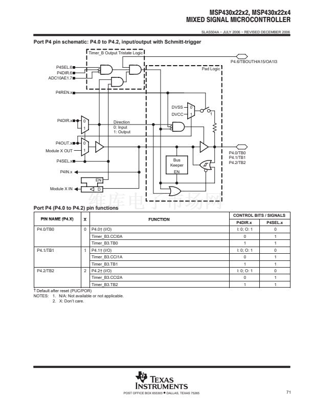
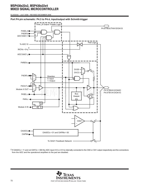
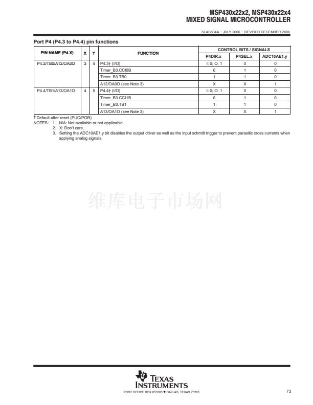
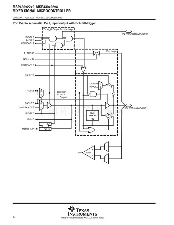
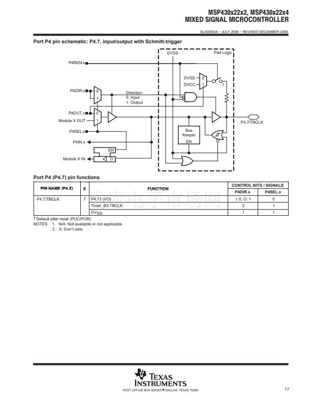
digital I/O
There are four 8-bit I/O ports implemented鈥攑orts P1, P2, P3, and P4:
D
D
D
D
D
All individual I/O bits are independently programmable.
Any combination of input, output, and interrupt conditions is possible.
Edge-selectable interrupt input capability for all the eight bits of port P1 and P2.
Read/write access to port-control registers is supported by all instructions.
Each I/O has an individually programmable pullup/pulldown resistor.
WDT+ watchdog timer
The primary function of the watchdog timer (WDT+) module is to perform a controlled system restart after a
software problem occurs. If the selected time interval expires, a system reset is generated. If the watchdog
function is not needed in an application, the module can be configured as an interval timer and can generate
interrupts at selected time intervals.
POST OFFICE BOX 655303
鈥?/div>
DALLAS, TEXAS 75265
17


 1
1
 2
2
 3
3
 4
4
 5
5
 6
6
 7
7
 8
8
 9
9
 10
10
 11
11
 12
12
 13
13
 14
14
 15
15
 16
16
 17
17
 18
18
 19
19
 20
20
 21
21
 22
22
 23
23
 24
24
 25
25
 26
26
 27
27
 28
28
 29
29
 30
30
 31
31
 32
32
 33
33
 34
34
 35
35
 36
36
 37
37
 38
38
 39
39
 40
40
 41
41
 42
42
 43
43
 44
44
 45
45
 46
46
 47
47
 48
48
 49
49
 50
50
 51
51
 52
52
 53
53
 54
54
 55
55
 56
56
 57
57
 58
58
 59
59
 60
60
 61
61
 62
62
 63
63
 64
64
 65
65
 66
66
 67
67
 68
68
 69
69
 70
70
 71
71
 72
72
 73
73
 74
74
 75
75
 76
76
 77
77
 78
78
 79
79
 80
80
 81
81
 82
82
 83
83
 84
84
 85
85
 86
86
 87
87
