Data Sheets
Sensitive SCRs
V
GT
(4) (12) (22)
I
H
(5) (19)
I
GM
(17)
V
GRM
P
GM
(17)
P
G(AV)
I
TSM
(6) (13)
dv/dt
di/dt
t
gt
(8)
t
q
(9)
l
2
t
T
C
=
-40 掳C
1
1
1
1
1
1
1
1
1
1
1
1
1
1
1
1
1
1
Volts
T
C
=
25 掳C
MAX
0.8
0.8
0.8
0.8
0.8
0.8
0.8
0.8
0.8
0.8
0.8
0.8
0.8
0.8
0.8
0.8
0.8
0.8
Volts/碌Sec
T
C
=
110 掳C
0.25
0.25
0.25
0.25
0.25
0.25
0.25
0.25
0.25
0.25
0.25
0.25
0.25
0.25
0.25
0.25
0.25
0.25
mAmps
MAX
6
6
6
8
8
8
6
6
6
8
8
8
6
6
6
8
8
8
Amps
1
1
1
1
1
1
1
1
1
1
1
1
1
1
1
1
1
1
Volts
MIN
6
6
6
6
6
6
6
6
6
6
6
6
6
6
6
6
6
6
Watts
1
1
1
1
1
1
1
1
1
1
1
1
1
1
1
1
1
1
Watts
0.1
0.1
0.1
0.1
0.1
0.1
0.1
0.1
0.1
0.1
0.1
0.1
0.1
0.1
0.1
0.1
0.1
0.1
Amps
60/50 Hz
100/83
100/83
100/83
100/83
100/83
100/83
100/83
100/83
100/83
100/83
100/83
100/83
100/83
100/83
100/83
100/83
100/83
100/83
T
C
= 110 掳C
TYP
10
8
8
10
8
8
10
8
8
10
8
8
10
8
8
10
8
8
Amps/碌Sec
100
100
100
100
100
100
100
100
100
100
100
100
100
100
100
100
100
100
碌Sec
TYP
4
4
4
5
5
5
4
4
4
5
5
5
4
4
4
5
5
5
碌Sec
MAX
50
50
50
45
45
45
50
50
50
45
45
45
50
50
50
45
45
45
Amps
2
Sec
41
41
41
41
41
41
41
41
41
41
41
41
41
41
41
41
41
41
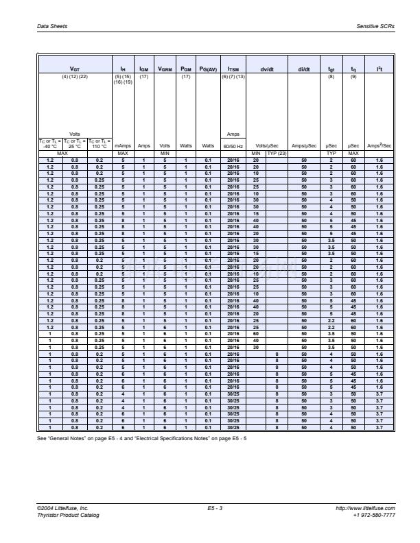
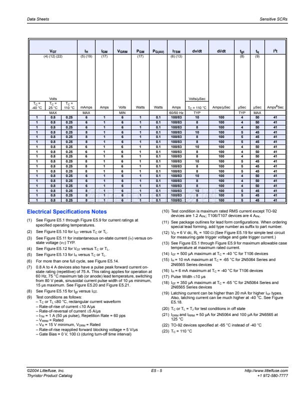
Electrical Specifications Notes
(1)
(2)
(3)
(4)
(5)
(6)
(7)
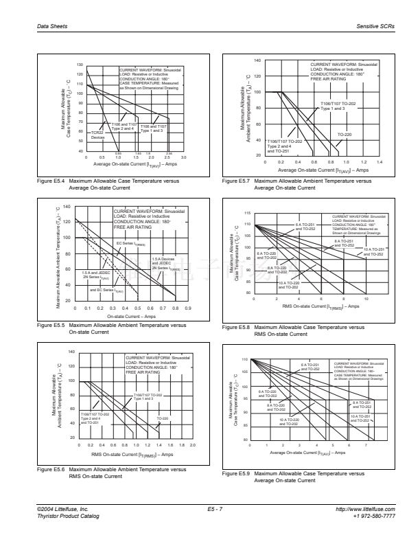
See Figure E5.1 through Figure E5.9 for current ratings at
specified operating temperatures.
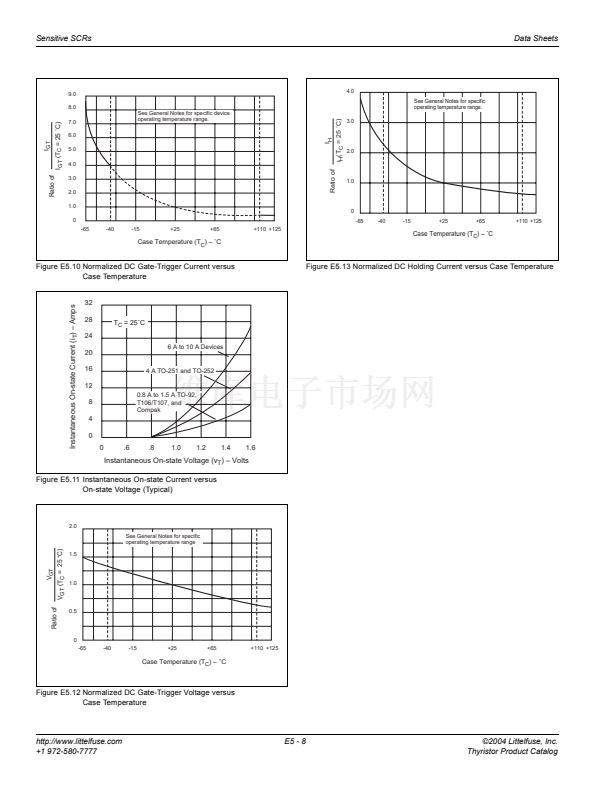
See Figure E5.10 for I
GT
versus T
C
or T
L
.
See Figure E5.11 for instantaneous on-state current (i
T
) versus on-
state voltage (v
T
) TYP.
See Figure E5.12 for V
GT
versus T
C
or T
L
.
See Figure E5.13 for I
H
versus T
C
or T
L
.
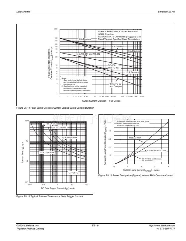
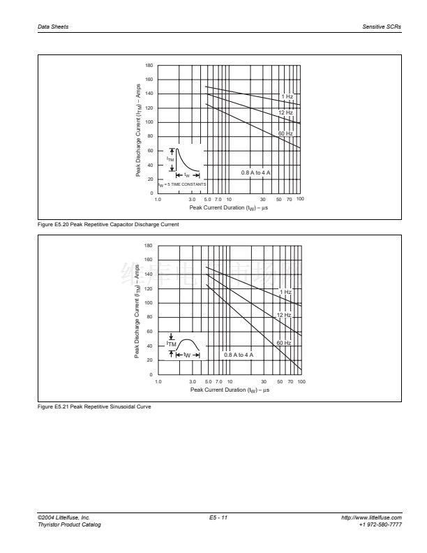
For more than one full cycle, see Figure E5.14.
0.8 A to 4 A devices also have a pulse peak forward current on-
state rating (repetitive) of 75 A. This rating applies for operation at
60 Hz, 75 掳C maximum tab (or anode) lead temperature, switching
from 80 V peak, sinusoidal current pulse width of 10 碌s minimum,
15 碌s maximum. See Figure E5.20 and Figure E5.21.
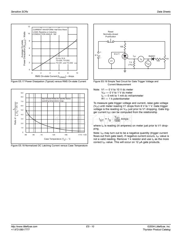
See Figure E5.15 for t
gt
versus I
GT
.
Test conditions as follows:
鈥?T
C
or T
L
鈮?0
掳C, rectangular current waveform
鈥?Rate-of-rise of current
鈮?0
A/碌s
鈥?Rate-of-reversal of current
鈮?
A/碌s
鈥?I
TM
= 1 A (50 碌s pulse), Repetition Rate = 60 pps
鈥?V
RRM
= Rated
鈥?V
R
= 15 V minimum, V
DRM
= Rated
鈥?Rate-of-rise reapplied forward blocking voltage = 5 V/碌s
鈥?Gate Bias = 0 V, 100
鈩?/div>
(during turn-off time interval)
(10) Test condition is maximum rated RMS current except TO-92
devices are 1.2 A
PK
; T106/T107 devices are 4 A
PK
.
(11) See package outlines for lead form configurations. When ordering
special lead forming, add type number as suffix to part number.
(12) V
D
= 6 V dc, R
L
= 100
鈩?/div>
(See Figure E5.19 for simple test circuit
for measuring gate trigger voltage and gate trigger current.)
(13) See Figure E5.1 through Figure E5.9 for maximum allowable case
temperature at maximum rated current.
(14) I
GT
= 500 碌A maximum at T
C
= -40 掳C for T106 devices
(15) I
H
= 10 mA maximum at T
C
= -65 掳C for 2N5064 Series and
2N6565 Series devices
(16) I
H
= 6 mA maximum at T
C
= -40 掳C for T106 devices
(17) Pulse Width
鈮?0
碌s
(18) I
GT
= 350 碌A maximum at T
C
= -65 掳C for 2N5064 Series and
2N6565 Series devices
(19) Latching current can be higher than 20 mA for higher I
GT
types.
Also, latching current can be much higher at -40 掳C. See Figure
E5.18.
(20) T
C
or T
L
= T
J
for test conditions in off state
(21) I
DRM
and I
RRM
= 50 碌A for 2N5064 and 100 碌A for 2N6565 at
125 掳C
(22) TO-92 devices specified at -65 掳C instead of -40 掳C
(23) T
C
= 110 掳C
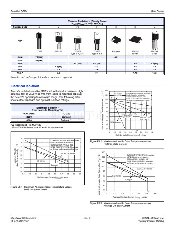
(8)
(9)
漏2004 Littelfuse, Inc.
Thyristor Product Catalog
E5 - 5
http://www.littelfuse.com
+1 972-580-7777


 1
1
 2
2
 3
3
 4
4
 5
5
 6
6
 7
7
 8
8
 9
9
 10
10
 11
11
 12
12
