鈥?/div>
V1
4
D.U.T.
I
GT
I
G
1k
(1%)
IN4001
100
V
GT
R1
2
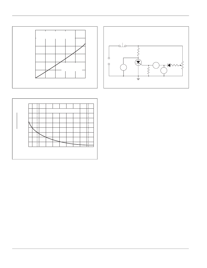
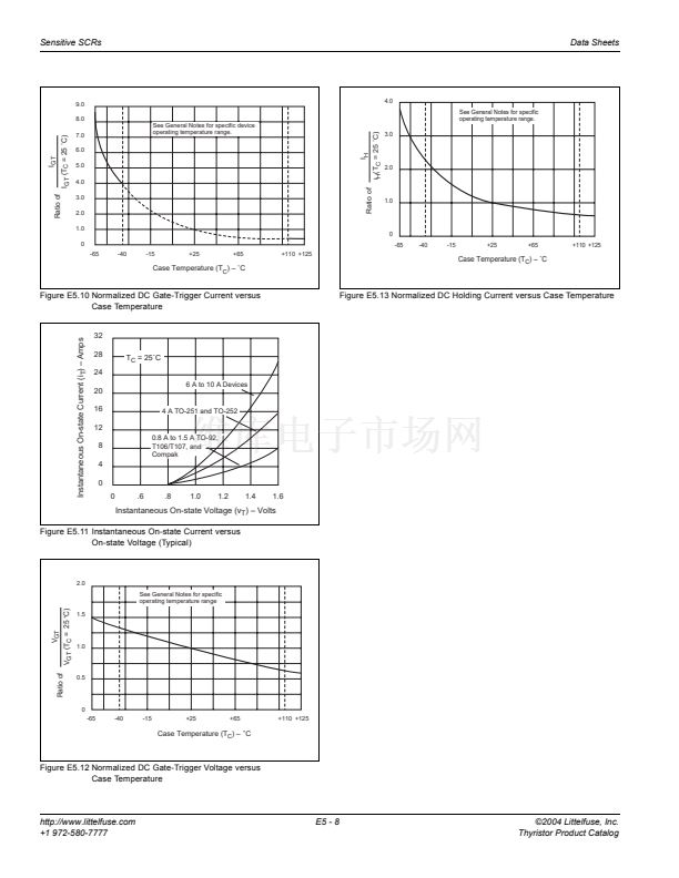
6 A to 10 A
TO-220, TO-202,
TO-251, and TO-252
0
0
2
4
6
8
10
RMS On-state Current [I
T(RMS)
] 鈥?Amps
Figure E5.17 Power Dissipation (Typical) versus RMS On-state Current
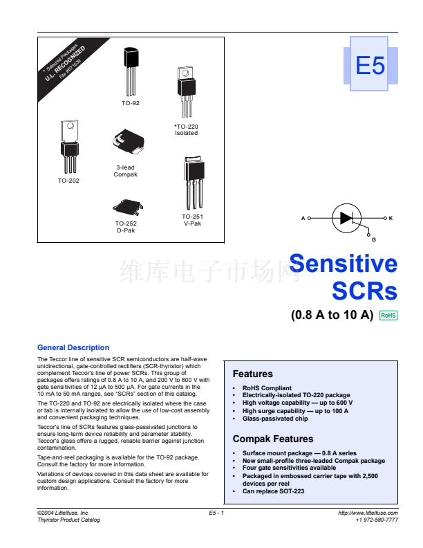
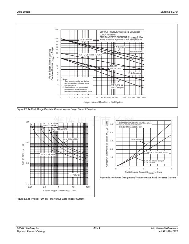
Figure E5.19 Simple Test Circuit for Gate Trigger Voltage and
Current Measurement
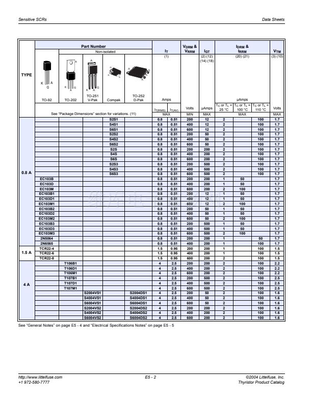
9.0
8.0
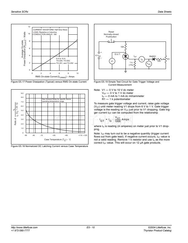
See General Notes for specific device
operating temperature range.
Note: V1 鈥?0 V to 10 V dc meter
V
GT
鈥?0 V to 1 V dc meter
I
G
鈥?0 mA to 1 mA dc milliammeter
R1 鈥?1 k potentiometer
To measure gate trigger voltage and current, raise gate voltage
(V
GT
) until meter reading V1 drops from 6 V to 1 V. Gate trigger
voltage is the reading on V
GT
just prior to V1 dropping. Gate trig-
ger current I
GT
can be computed from the relationship
V
GT
I GT = I G
鈥?/div>
------------ Amps
-
1000
where I
G
is reading (in amperes) on meter just prior to V1 drop-
ping.
IL
(TC = 25 藲C)
IL
Ratio of
7.0
6.0
5.0
4.0
3.0
2.0
1.0
0
-65
-40
-15
+25
+65
+110 +125
Case Temperature (TC) 鈥?藲C
Note: I
GT
may turn out to be a negative quantity (trigger current
flows out from gate lead). If negative current occurs, I
GT
value is
not a valid reading. Remove 1 k resistor and use I
G
as the more
correct I
GT
value. This will occur on 12
碌
A gate products.
Figure E5.18 Normalized DC Latching Current versus Case Temperature
http://www.littelfuse.com
+1 972-580-7777
E5 - 10
漏2004 Littelfuse, Inc.
Thyristor Product Catalog


 1
1
 2
2
 3
3
 4
4
 5
5
 6
6
 7
7
 8
8
 9
9
 10
10
 11
11
 12
12
