鉁?/div>
7 Matrix LED Display Driver
register are parallel loaded into a 16-bit latch. The 16
bits in the latch are then decoded and executed.
The MAX6952 is written to using the following
sequence:
1)
2)
3)
Take CLK low.
Take
CS
low. This enables the internal 16-bit shift
register.
Clock 16 bits of data into DIN, D15 first to D0 last,
observing the setup and hold times. Bit D15 is low,
indicating a write command.
Take
CS
high (while CLK is still high after clocking
in the last data bit).
Take CLK low.
is represented by 2 bytes of memory, 1 byte in plane P0
and the other in plane P1. The digit registers are mapped
so that a digit鈥檚 data can be updated in plane P0, or
plane P1, or both planes at the same time (Table 4).
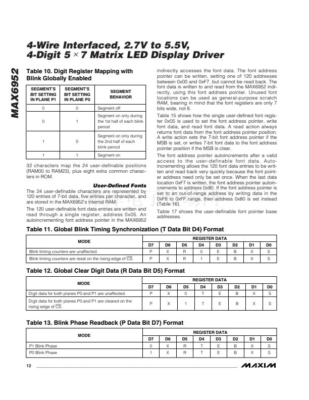
If the blink function is disabled through the Blink Enable
Bit E (Table 9) in the configuration register, then the
digit register data in plane P0 is used to multiplex the
display. The digit register data in P1 is not used. If the
blink function is enabled, then the digit register data in
both plane P0 and plane P1 are alternately used to mul-
tiplex the display. Blinking is achieved by multiplexing
the LED display using data planes P0 and P1 on alter-
nate phases of the blink clock (Table 10).
The data in the digit registers does not control the digit
segments directly. Instead, the register data is used to
address a character generator, which stores the data of
a 128-character font (Table 14). The lower 7 bits of the
digit data (D6 to D0) select the character from the font.
The most-significant bit of the register data (D7) selects
whether the font data is used directly (D7 = 0) or
whether the font data is inverted (D7 = 1). The inversion
feature can be used to enhance the appearance of
bicolor displays by displaying, for example, a red char-
acter on a green background.
MAX6952
4)
5)
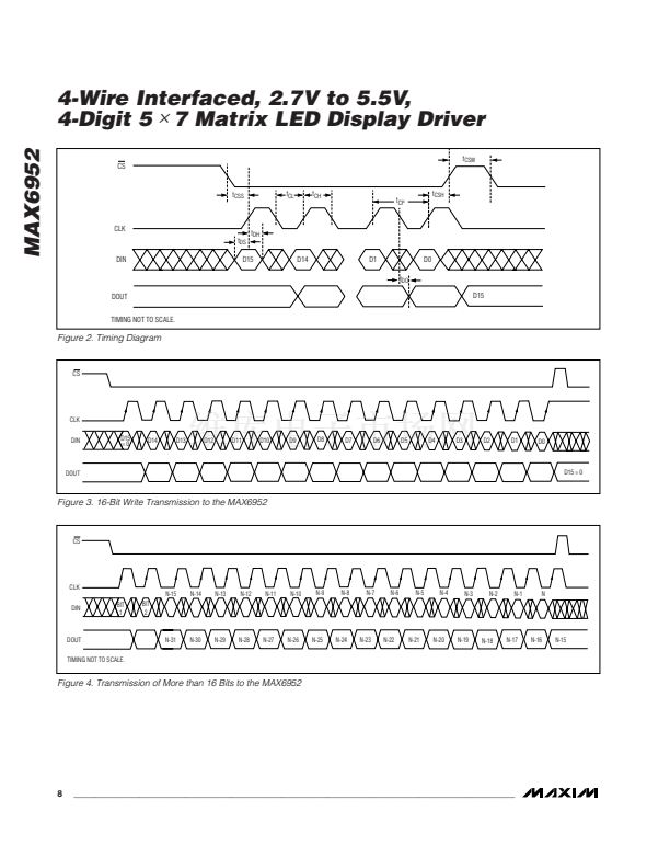
Figure 3 shows a write operation when 16 bits are
transmitted.
If fewer or greater than 16 bits are clocked into the
MAX6952 between taking
CS
low and taking
CS
high
again, the MAX6952 stores the last 16 bits received,
including the previous transmission(s). The general
case is when n bits (where n > 16) are transmitted to
the MAX6952. The last bits comprising bits {n-15} to {n}
are retained and are parallel loaded into the 16-bit latch
as bits D15 to D0, respectively (Figure 4).
Reading Device Registers
Any register data within the MAX6952 may be read by
sending a logic high to bit D15. The sequence is:
1) Take CLK low.
2) Take
CS
low. This enables the internal 16-bit shift
register.
3) Clock 16 bits of data into DIN, D15 first to D0 last,
observing the setup and hold times. Bit D15 is high,
indicating a read command and bits D14 through
D8 contain the address of the register to read. Bits
D7 to D0 contain dummy data, which is discarded.
4) Take
CS
high. Positions D7 through D0 in the shift
register are now loaded with the data in the register
addressed by bits D15 through D8. Bits
5) Take CLK low.
6) Issue another read or write command (which can
be a no-op), and examine the bit stream at DOUT;
the second 8 bits are the contents of the register
addressed by bits D14 through D8 in step 3.
Display Blink Mode
The display blinking facility, when enabled, makes the
driver flip automatically between displaying the digit
register data in planes P0 and P1. If the digit register
data for any digit is different in the two planes, then that
digit appears to flip between two characters. To make a
character appear to blink on or off, write the character
to one plane, and use the blank character (0x20) for the
other plane. Once blinking has been configured, it con-
tinues automatically without further intervention.
Blink Speed
The blink speed is determined by frequency of the mul-
tiplex clock, OSC, and by setting the Blink Rate
Selection Bit B (Table 8) in the configuration register.
The Blink Rate Selection Bit B sets either fast or slow
blink speed for the whole display.
Initial Power-Up
On initial power-up, all control registers are reset, the
display is blanked, intensities are set to minimum, and
shutdown is enabled (Table 5).
Digit Registers
The MAX6952 uses eight digit registers to store the char-
acters that the user wishes to display on the four 5
鉁?/div>
7
LED digits. These digit registers are implemented with
two planes of 4 bytes, called P0 and P1. Each LED digit
Configuration Register
The configuration register is used to enter and exit
shutdown, select the blink rate, globally enable and
disable the blink function, globally clear the digit data,
and reset the blink timing (Table 6).
_______________________________________________________________________________________
7


 1
1
 2
2
 3
3
 4
4
 5
5
 6
6
 7
7
 8
8
 9
9
 10
10
 11
11
 12
12
 13
13
 14
14
 15
15
 16
16
 17
17
 18
18
 19
19
 20
20
 21
21
