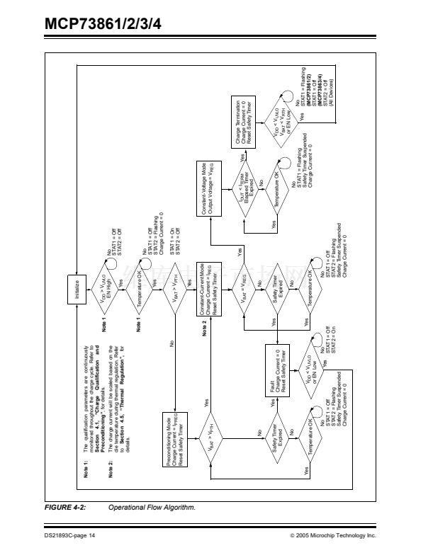
FIGURE 4-2:
Initialize
DS21893C-page 14
Note 1
Note 1:
The qualification parameters are continuously
monitored throughout the charge cycle. Refer to
Section 4.1, 鈥淐harge Qualification and
Preconditioning鈥?/div>
, for details.
V
DD
> V
UVLO
EN High
Yes
No
STAT1 = Off
STAT2 = Off
Note 2:
The charge current will be scaled based on the
die temperature during thermal regulation. Refer
to
Section 4.5, 鈥淭hermal Regulation鈥?
for
details.
Note 1
Temperature OK
Yes
No
STAT1 = Off
STAT2 = Flashing
Charge Current = 0
STAT1 = On
STAT2 = Off
MCP73861/2/3/4
Preconditioning Mode
Charge Current = I
PREG
Reset Safety Timer
No
V
BAT
> V
PTH
Yes
Note 2
Operational Flow Algorithm.
Yes
Constant-Current Mode
Charge Current = I
REG
Reset Safety Timer
Constant-Voltage Mode
Output Voltage = V
REG
V
BAT
= V
REG
No
Yes
Yes
Safety Timer
Expired
No
Yes
No
STAT1 = Off
STAT2 = On
Yes
Yes
I
OUT
< I
TERM
Elapsed Timer
Expired
No
Temperature OK
Yes
Fault
Charge Current = 0
Reset Safety Timer
Yes
V
DD
< V
UVLO
or EN Low
Temperature OK
No
STAT1 = Off
STAT2 = Flashing
Safety Timer Suspended
Charge Current = 0
No
STAT1 = Flashing
Safety Timer Suspended
Charge Current = 0
No
Yes
STAT1 = Off
STAT2 = Flashing
Safety Timer Suspended
Charge Current = 0
V
BAT
> V
PTH
Charge Termination
Charge Current = 0
Reset Safety Timer
No
Safety Timer
Expired
No
V
DD
< V
UVLO
V
BAT
< V
RTH
or EN Low
漏
2005 Microchip Technology Inc.
Yes
Temperature OK
No
STAT1 = Flashing
(MCP73861/2)
STAT1 = Off
(MCP73863/4)
STAT2 = Off
(All Devices)


 1
1
 2
2
 3
3
 4
4
 5
5
 6
6
 7
7
 8
8
 9
9
 10
10
 11
11
 12
12
 13
13
 14
14
 15
15
 16
16
 17
17
 18
18
 19
19
 20
20
 21
21
 22
22
 23
23
 24
24
 25
25
 26
26
 27
27
 28
28
