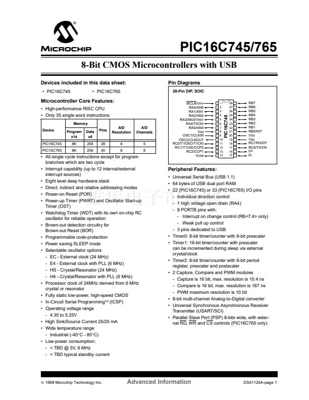
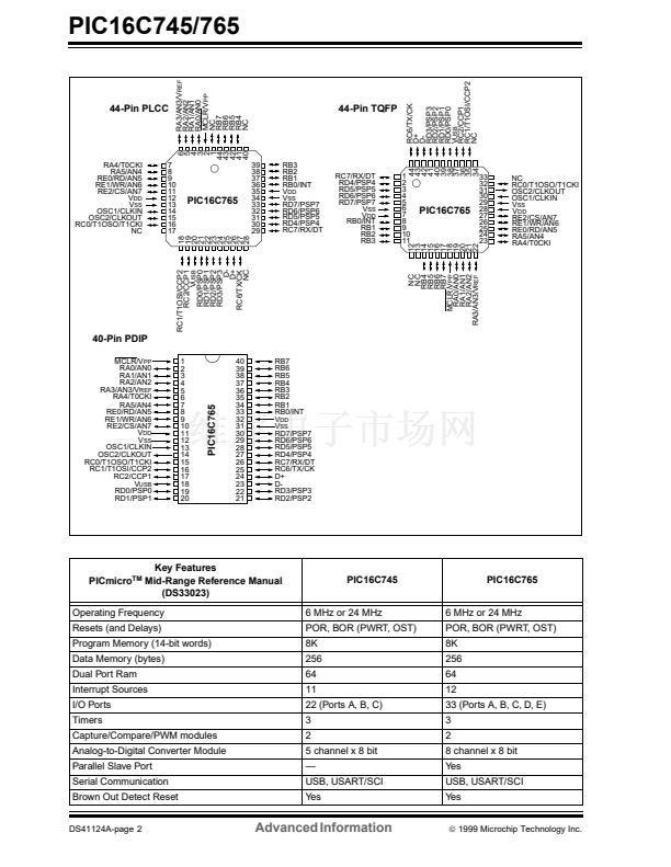
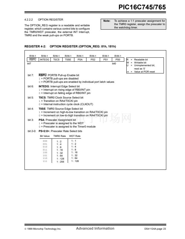
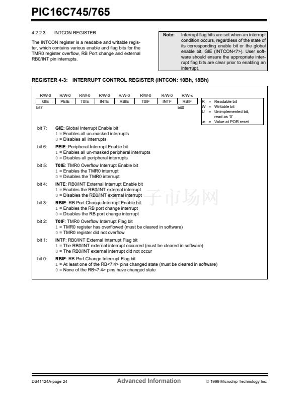
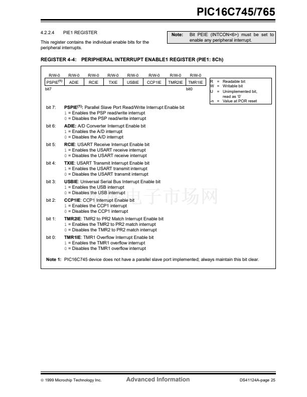
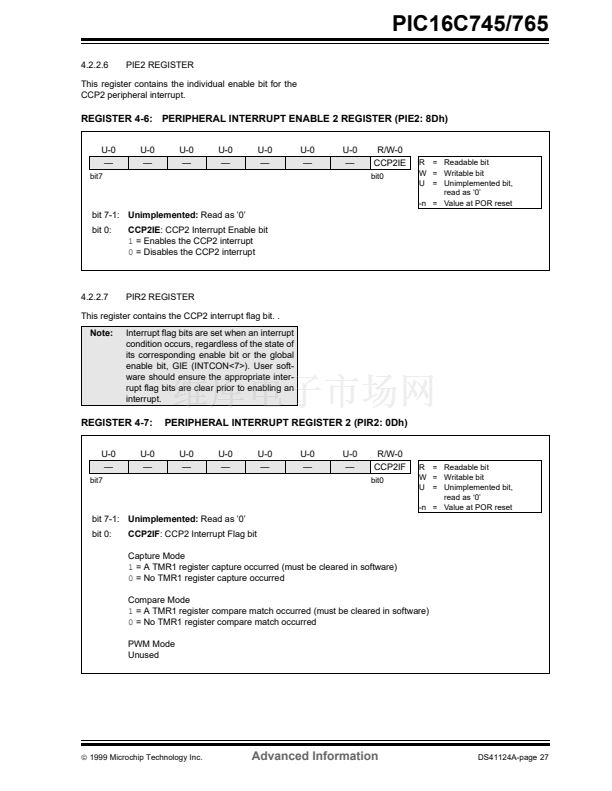
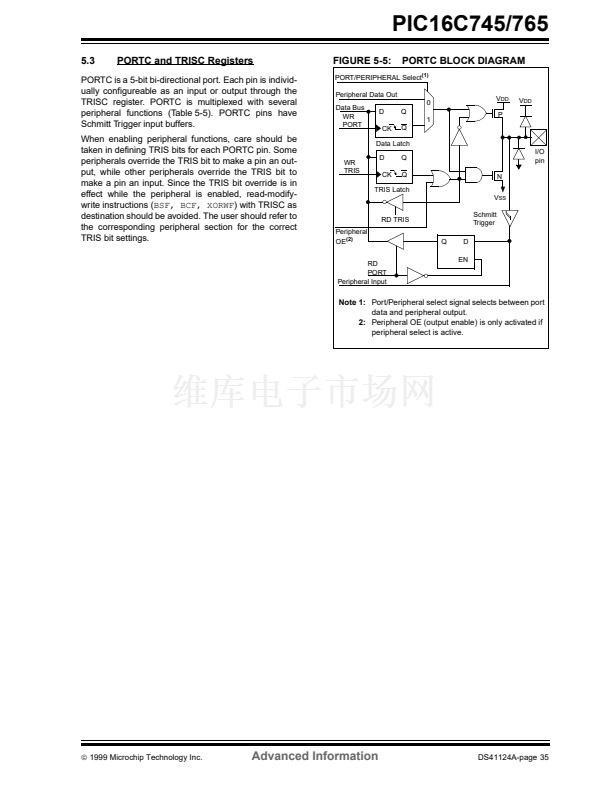
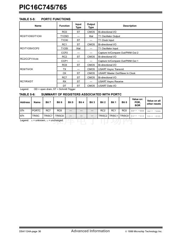
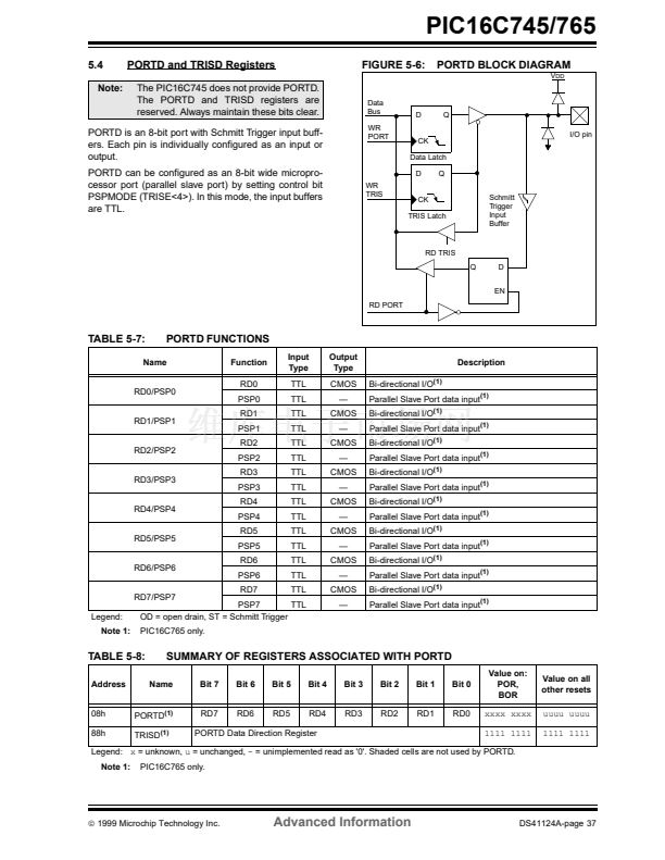
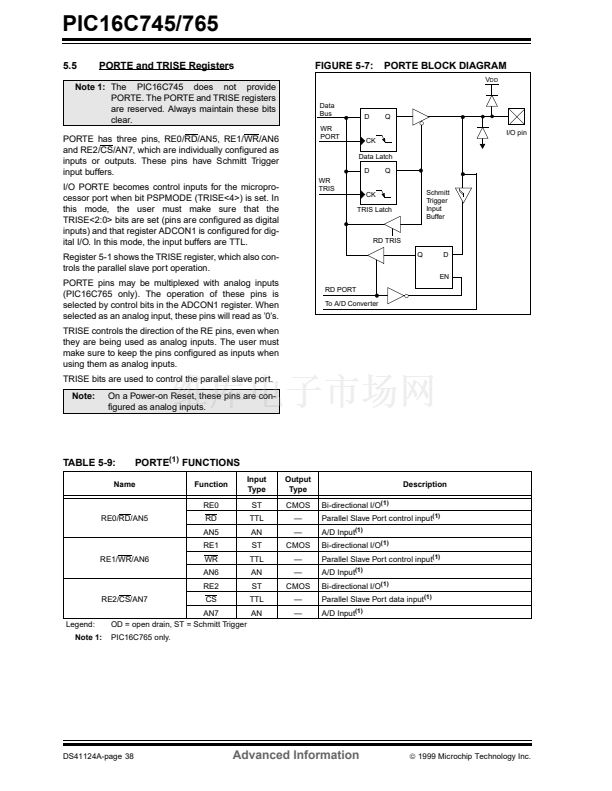
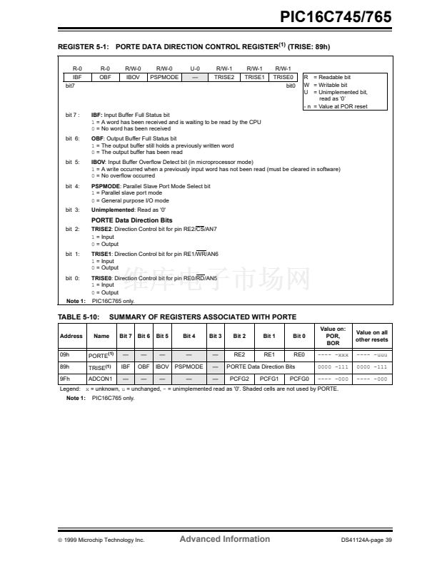
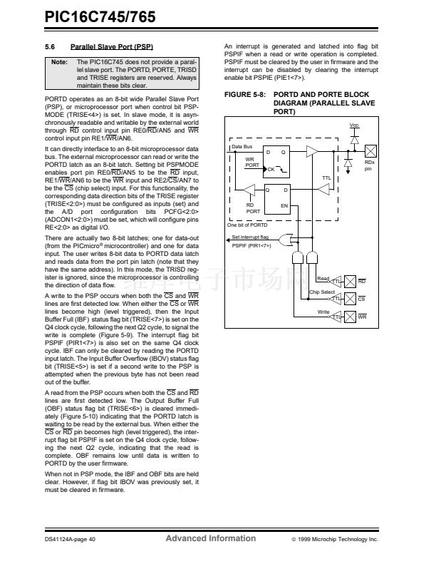
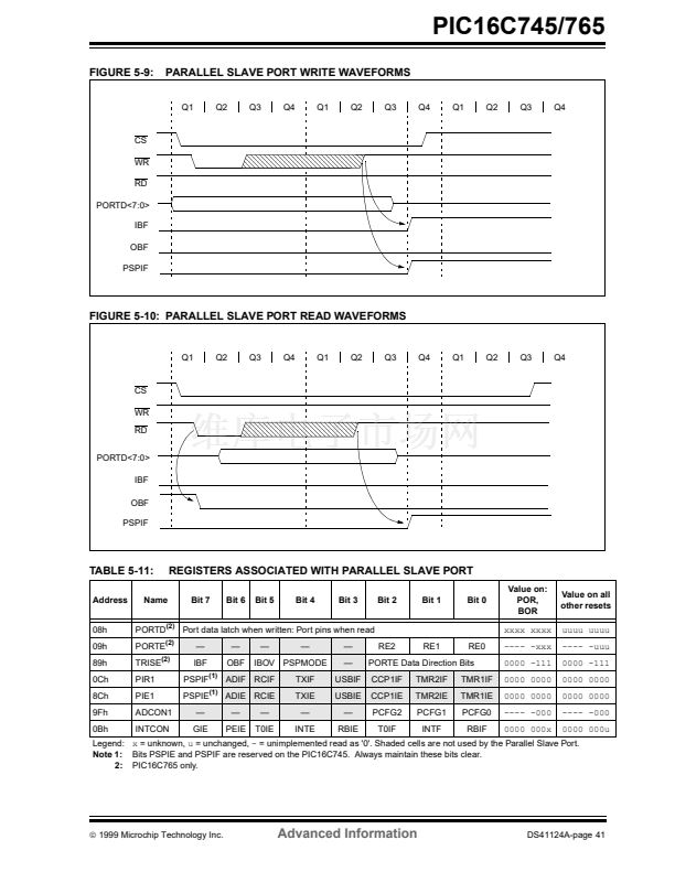
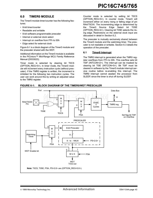
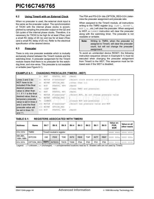
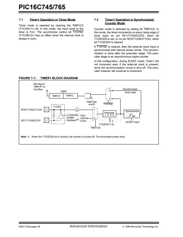
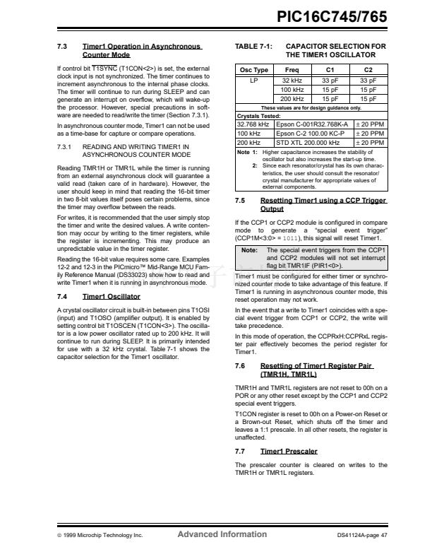
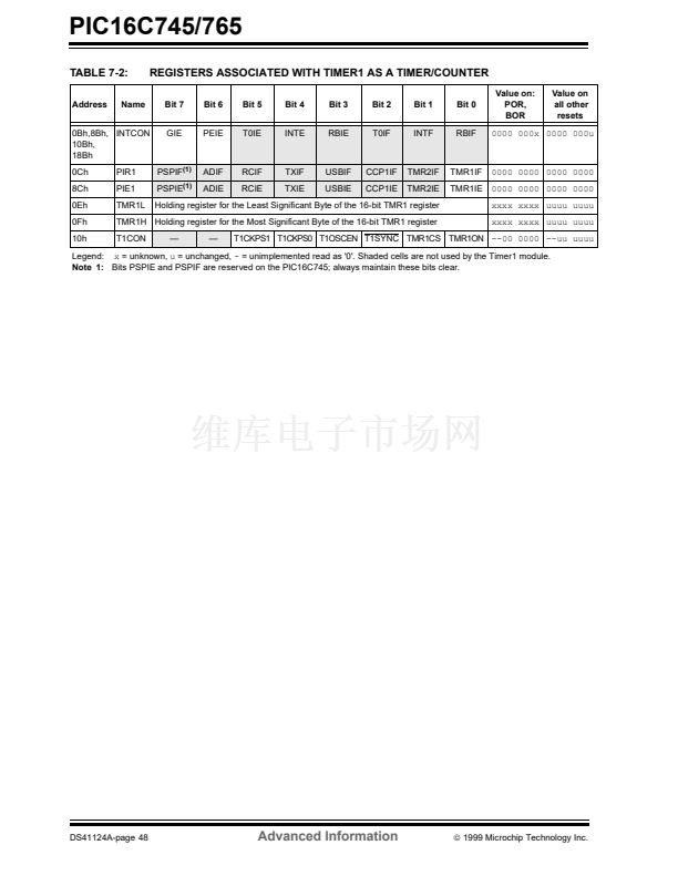
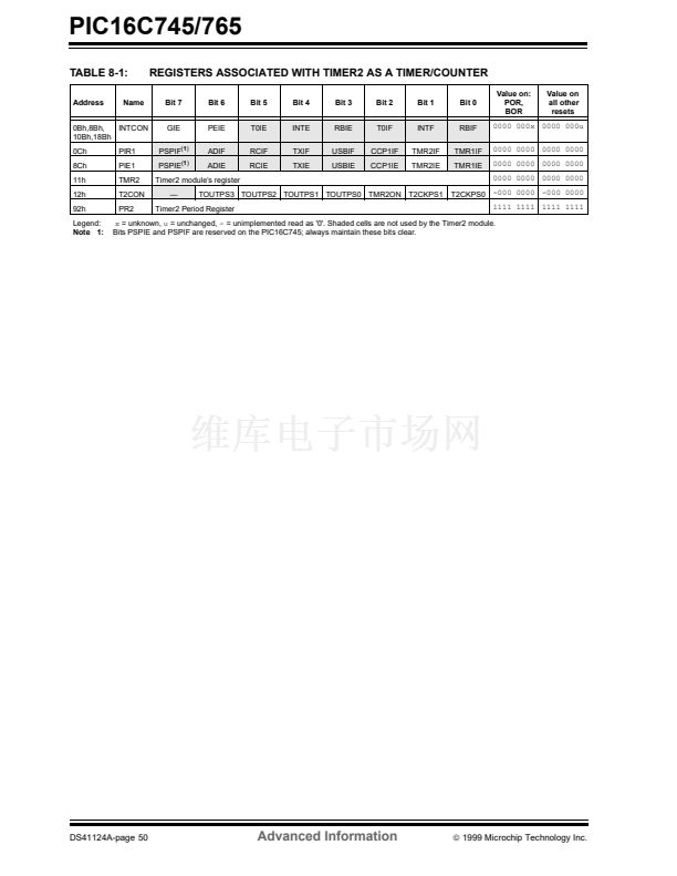
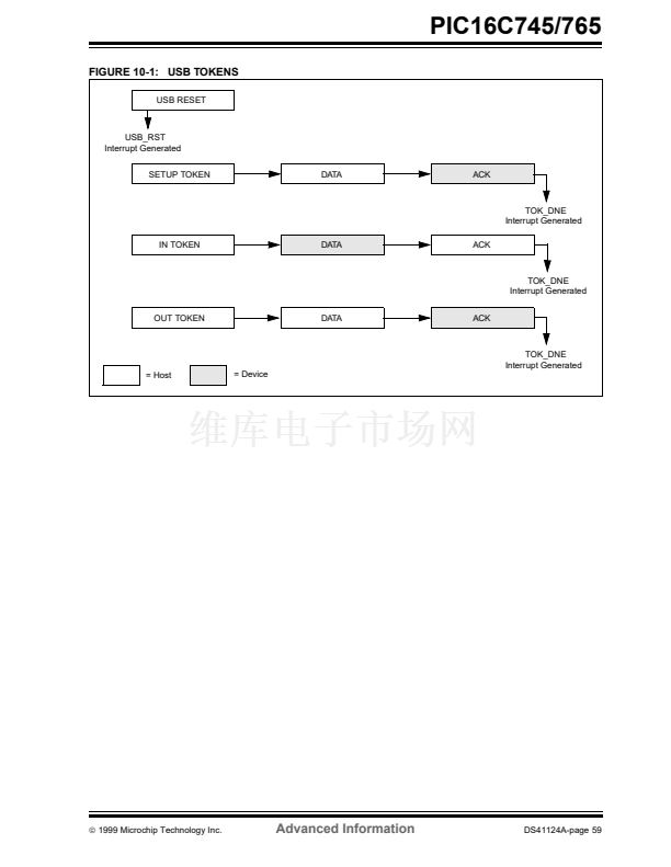
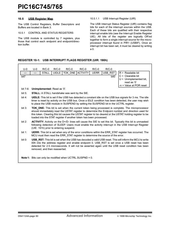
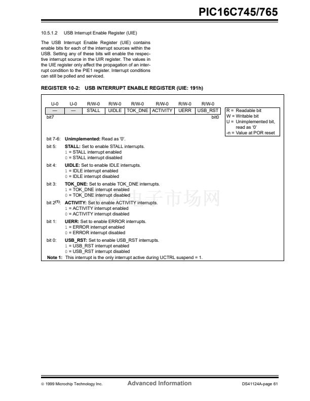
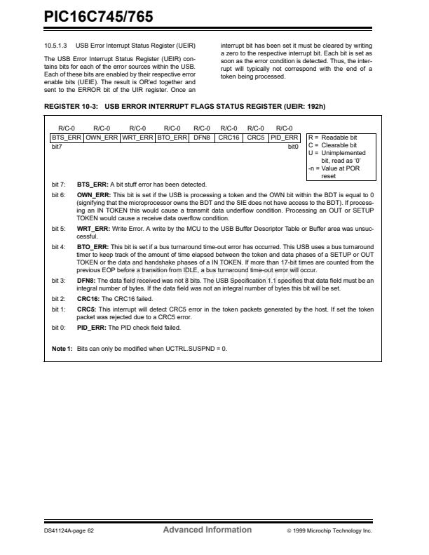
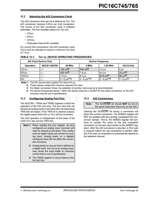
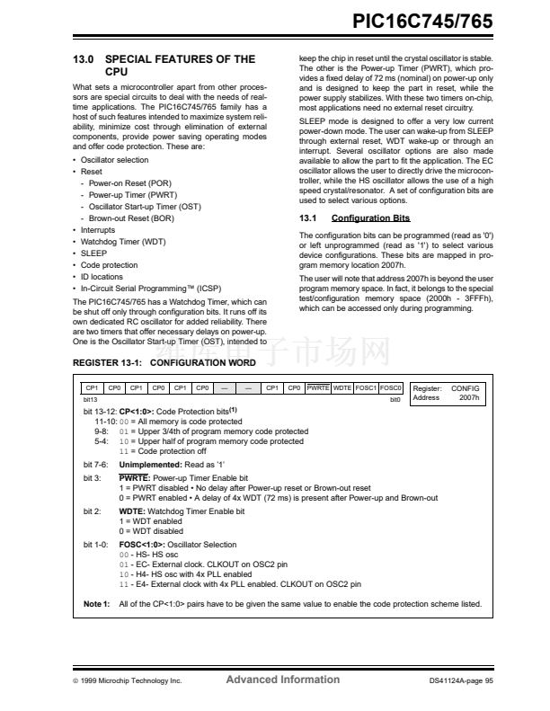
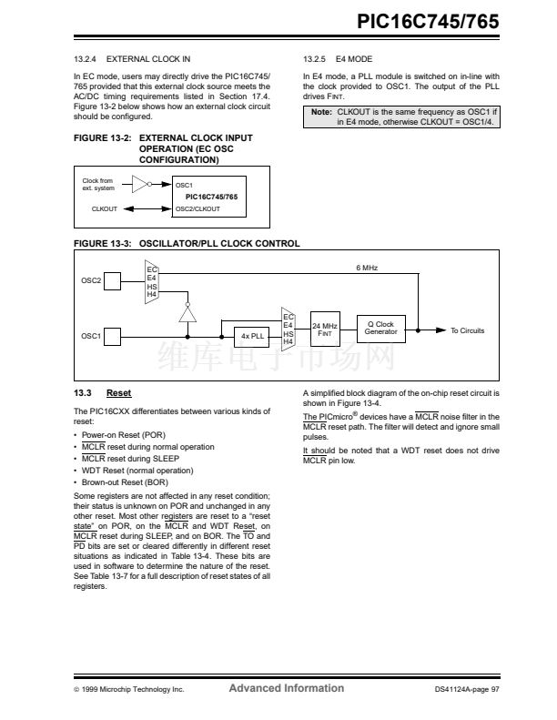
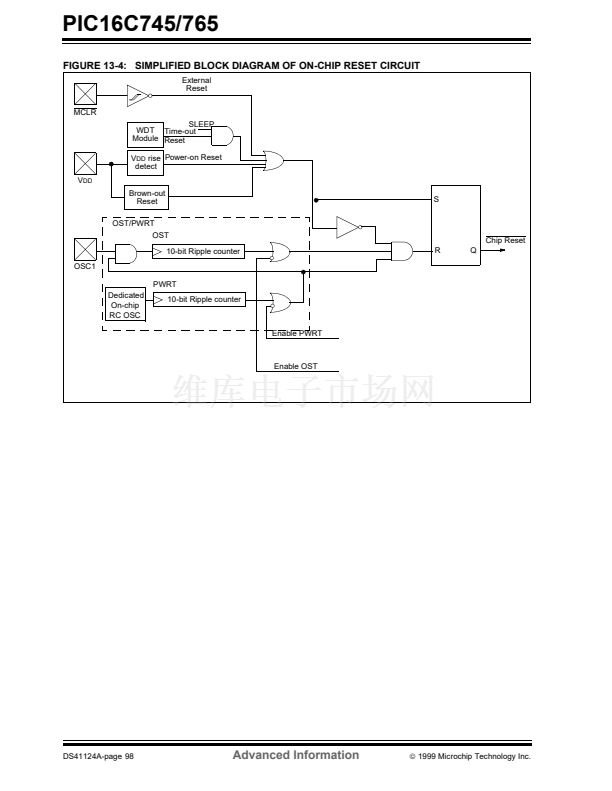
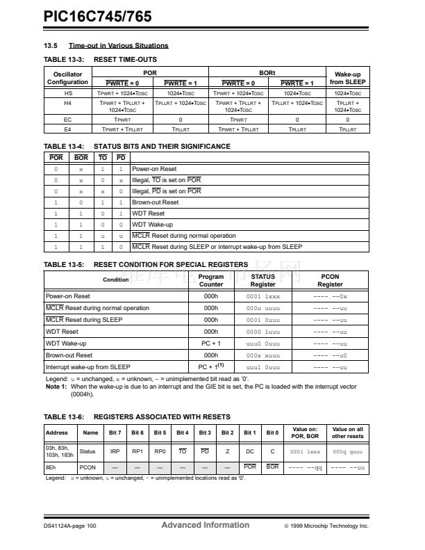
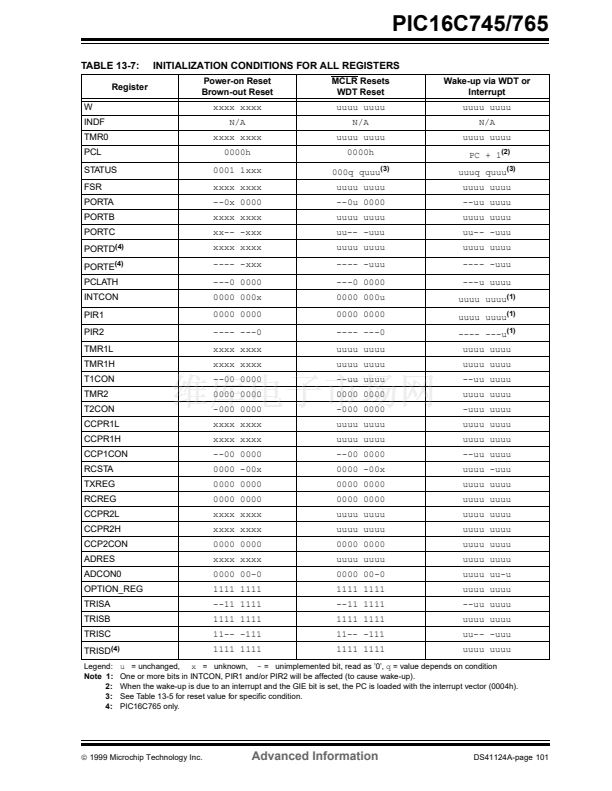
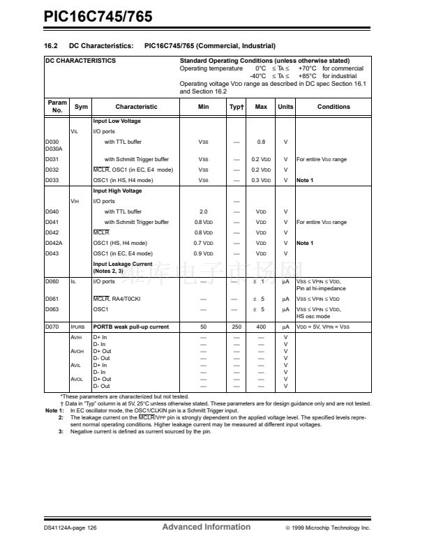
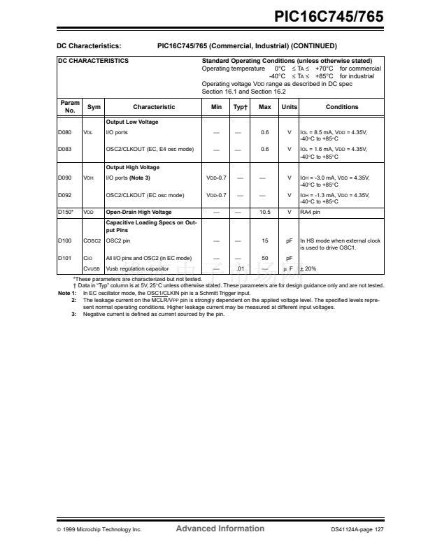
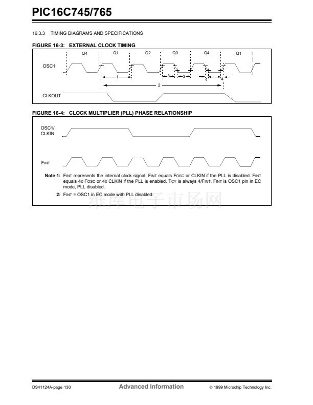
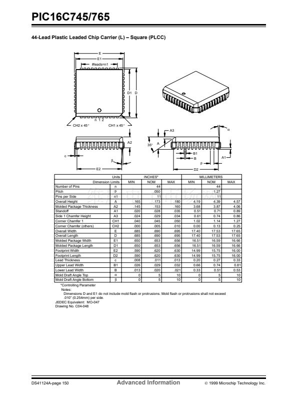
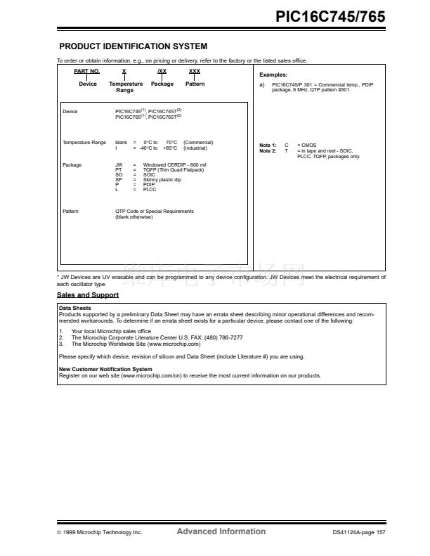
PIC16C745/765
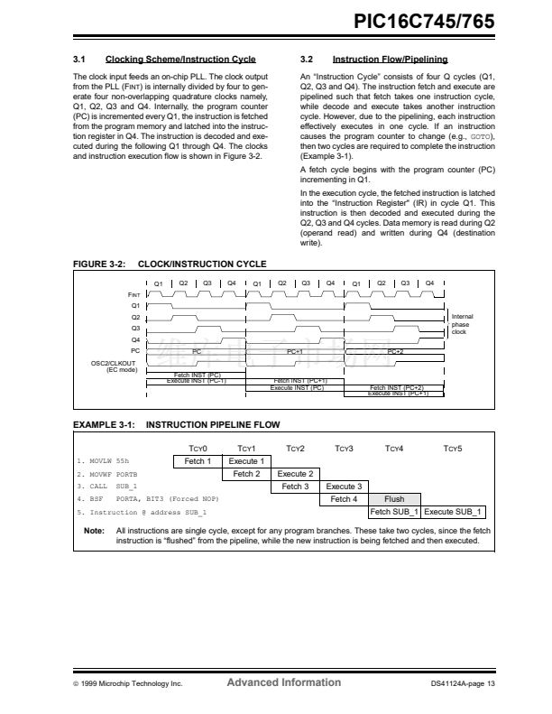
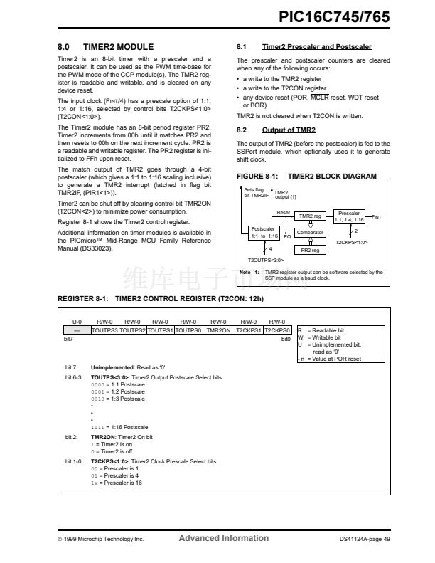
10.0
10.1
UNIVERSAL SERIAL BUS
Overview
10.1.2
FRAMES
This section introduces a minimum amount of informa-
tion on USB. If you already have basic knowledge of
USB, you can safely skip this section. If terms like
Enumeration, Endpoint, IN/OUT Transactions, Trans-
fers and Low Speed/Full Speed are foreign to you,
read on.
USB was developed to address the increased connec-
tivity needs of PC鈥檚 in the PC 2000 specification.
There was a base requirement to increase the band-
width and number of devices, which could be attached.
Also desired were the ability for hot swapping, user
friendly operation, robust communications and low
cost. The primary promoters of USB are Intel, Com-
paq, Microsoft and NEC.
USB is implemented as a Tiered Star topology, with
the host at the top, hubs in the middle, spreading out
to the individual devices at the end. USB is limited to
127 devices on the bus, and the tree cannot be more
than 6 levels deep.
USB is a host centric architecture. The host is always
the master. Devices are not allowed to 鈥渟peak鈥?unless
鈥渟poken to鈥?by the host.
Transfers take place at one of two speeds. Full Speed
is 12 Mb/s and Low Speed is 1.5 Mb/s. Full Speed
covers the middle ground of data intensive audio and
compressed video applications, while low speed sup-
ports less data intensive applications.
10.1.1
TRANSFER PROTOCOLS
Information communicated on the bus is grouped in a
format called Frames. Each Frame is 1 ms in duration
and is composed of multiple transfers. Each transfer
type can be repeated more than once within a frame.
10.1.3
POWER
Power has always been a concern with any device.
With USB, 5 volt power is now available directly from
the bus. Devices may be self-powered or bus-pow-
ered. Self-powered devices will draw power from a
wall adapter or power brick. On the other hand, bus-
powered devices will draw power directly from the
USB bus itself. There are limits to how much power
can be drawn from the USB bus. Power is expressed
in terms of 鈥渦nit loads鈥?(鈮?00 mA). All devices, includ-
ing Hubs, are guaranteed at least 1 unit load (low
power), but must negotiate with the host for up to 5
unit loads (high power). If the host determines that the
bus as currently configured cannot support a device鈥檚
request for more unit loads, the device will be denied
the extra unit loads and must remain in a low power
configuration.
10.1.4
END POINTS
Four transfer protocols are defined, each with
attributes:
- Isochronous Transfers, meaning equal time,
guarantee a fixed amount of data at a fixed
rate. This mode trades off guaranteed data
accuracy for guaranteed timeliness. Data
validity is not checked because there isn鈥檛
time to re-send bad packets anyway and the
consequences of bad data are not cata-
strophic.
- Bulk Transfers are the converse of Isocho-
nous. Data accuracy is guaranteed, but time-
liness is not.
- Interrupt Transfers are designed to communi-
cate with devices which have a moderate
data rate requirement. Human Interface
Devices like keyboards are but one example.
For Interrupt Transfers, the key is the desire
to transfer data at regular intervals. USB peri-
odically polls these devices at a fixed rate to
see if there is data to transfer.
- Control Transfers are used for configuration
purposes.
At the lowest level, each device controls one or more
endpoints. An endpoint can be thought of as a virtual
port. Endpoints are used to communicate with a
device鈥檚 functions. Each endpoint is a source or sink of
data. Endpoints have both an In and Out direction
associated with it. Each device must implement end-
point 0 to support Control Transfers for configuration.
There are a maximum of 15 endpoints available for
use by each full speed device and 6 endpoints for
each slow speed device. Remember that the bus is
host centric, so In/Out is with respect to the host and
not the device.
10.1.5
ENUMERATION
Prior to communicating on the bus, the host must see
that a new device has been connected and then go
through an 鈥渆numeration process鈥? This process
allows the host to ask the device to introduce itself,
and negotiate performance parameters, such as
power consumption, transfer protocol and polling rate.
The enumeration process is initiated by the host when
it detects that a new device has attached itself to the
bus. This takes place completely in the background
from the application process.
10.1.6
DESCRIPTORS
The USB specification requires a number of different
descriptors to provide information necessary to iden-
tify a device, specify its endpoints, and each endpoint鈥檚
function. The five general categories of descriptors are
Device, Configuration, Interface, End Point and String.
漏
1999 Microchip Technology Inc.
Advanced Information
DS41124A-page 57


 1
1
 2
2
 3
3
 4
4
 5
5
 6
6
 7
7
 8
8
 9
9
 10
10
 11
11
 12
12
 13
13
 14
14
 15
15
 16
16
 17
17
 18
18
 19
19
 20
20
 21
21
 22
22
 23
23
 24
24
 25
25
 26
26
 27
27
 28
28
 29
29
 30
30
 31
31
 32
32
 33
33
 34
34
 35
35
 36
36
 37
37
 38
38
 39
39
 40
40
 41
41
 42
42
 43
43
 44
44
 45
45
 46
46
 47
47
 48
48
 49
49
 50
50
 51
51
 52
52
 53
53
 54
54
 55
55
 56
56
 57
57
 58
58
 59
59
 60
60
 61
61
 62
62
 63
63
 64
64
 65
65
 66
66
 67
67
 68
68
 69
69
 70
70
 71
71
 72
72
 73
73
 74
74
 75
75
 76
76
 77
77
 78
78
 79
79
 80
80
 81
81
 82
82
 83
83
 84
84
 85
85
 86
86
 87
87
 88
88
 89
89
 90
90
 91
91
 92
92
 93
93
 94
94
 95
95
 96
96
 97
97
 98
98
 99
99
 100
100
 101
101
 102
102
 103
103
 104
104
 105
105
 106
106
 107
107
 108
108
 109
109
 110
110
 111
111
 112
112
 113
113
 114
114
 115
115
 116
116
 117
117
 118
118
 119
119
 120
120
 121
121
 122
122
 123
123
 124
124
 125
125
 126
126
 127
127
 128
128
 129
129
 130
130
 131
131
 132
132
 133
133
 134
134
 135
135
 136
136
 137
137
 138
138
 139
139
 140
140
 141
141
 142
142
 143
143
 144
144
 145
145
 146
146
 147
147
 148
148
 149
149
 150
150
 151
151
 152
152
 153
153
 154
154
 155
155
 156
156
 157
157
 158
158
