MSP430xW42x
MIXED SIGNAL MICROCONTROLLER
SLAS383A 鈭?OCTOBER 2003 鈭?REVISED AUGUST 2004
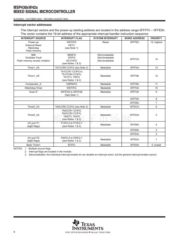
recommended operating conditions
PARAMETER
Supply voltage during program execution, SVS disabled
VCC (AVCC = DVCC = VCC)
Supply voltage during program execution, SVS enabled (see Note 1),
VCC (AVCC = DVCC = VCC)
Supply voltage during programming flash memory,
VCC (AVCC = DVCC = VCC)
Supply voltage, VSS (AVSS = DVSS = VSS)
Operating free-air temperature range, TA
LF selected, XTS_FLL=0
LFXT1 crystal frequency, f(LFXT1)
(see Note 2)
XT1 selected, XTS_FLL=1
XT1 selected, XTS_FLL=1
Processor frequency (signal MCLK), f(System)
MSP430xW42x
Watch crystal
Ceramic resonator
Crystal
VCC = 1.8 V
VCC = 3.6 V
450
1000
DC
DC
MSP430xW42x
MSP430xW42x
MSP430FW42x
MIN
1.8
2.2
2.7
0
鈭?0
32768
8000
8000
4.15
8
MHz
NOM
MAX
3.6
3.6
3.6
0
85
UNITS
V
V
V
V
掳C
Hz
kHz
kHz
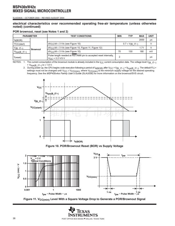
NOTES: 1. The minimum operating supply voltage is defined according to the trip point where POR is going active by decreasing supply voltage.
POR is going inactive when the supply voltage is raised above minimum supply voltage plus the hysteresis of the SVS circuitry.
2. In LF mode, the LFXT1 oscillator requires a watch crystal. In XT1 mode, LFXT1 accepts a ceramic resonator or a crystal.
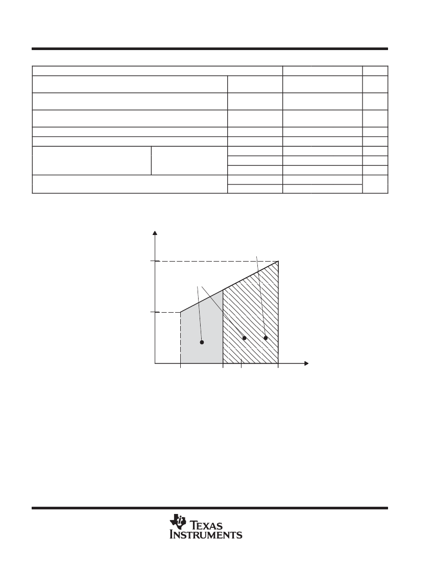
f(System) 鈭?Maximum Processor Frequency 鈭?MHz
f (MHz)
Supply Voltage Range
During Programming of
the Flash Memory
8 MHz
Supply Voltage Range During
Program Execution
4.15 MHz
1.8 V
2.7 V
VCC 鈭?Supply Voltage 鈭?V
Figure 1. Maximum Frequency vs Supply Voltage
18
POST OFFICE BOX 655303
鈥?/div>
DALLAS, TEXAS 75265
脦脦脦脦脦脦
脦脦脦脦脦脦
脦脦脦脦脦脦
脦脦脦脦脦脦
脦脦脦脦脦脦
脦脦脦脦脦脦
脦脦脦脦脦脦
脦脦脦脦脦脦
脦脦脦脦脦脦
脦脦脦脦脦脦
脦脦脦脦脦脦
3V
3.6 V


 1
1
 2
2
 3
3
 4
4
 5
5
 6
6
 7
7
 8
8
 9
9
 10
10
 11
11
 12
12
 13
13
 14
14
 15
15
 16
16
 17
17
 18
18
 19
19
 20
20
 21
21
 22
22
 23
23
 24
24
 25
25
 26
26
 27
27
 28
28
 29
29
 30
30
 31
31
 32
32
 33
33
 34
34
 35
35
 36
36
 37
37
 38
38
 39
39
 40
40
 41
41
 42
42
 43
43
 44
44
 45
45
 46
46
 47
47
 48
48
 49
49
 50
50
 51
51
 52
52
 53
53
