MSP430xW42x
MIXED SIGNAL MICROCONTROLLER
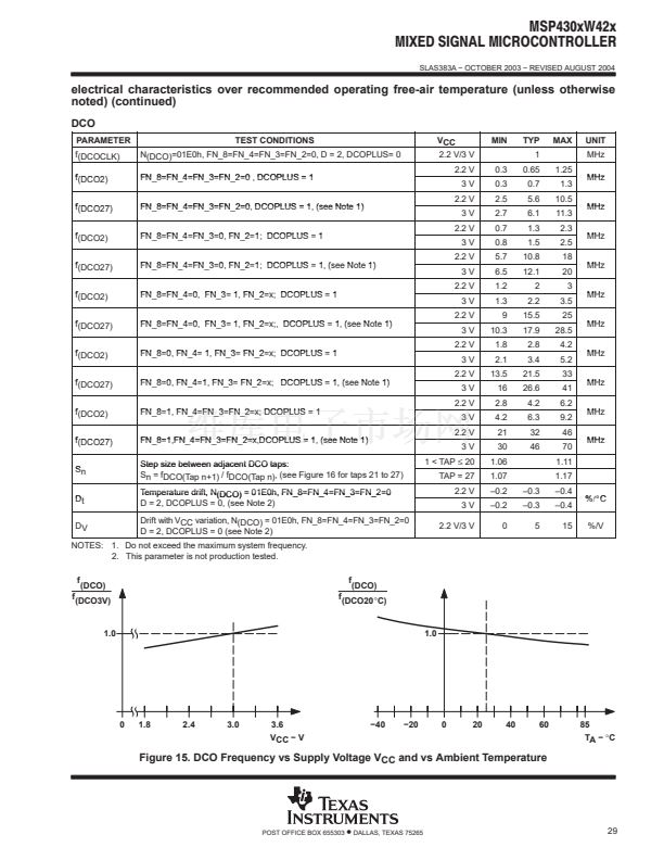
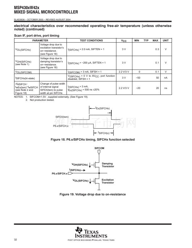
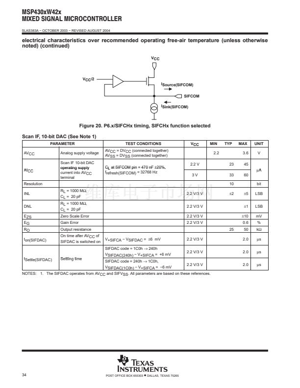
SLAS383A 鈭?OCTOBER 2003 鈭?REVISED AUGUST 2004
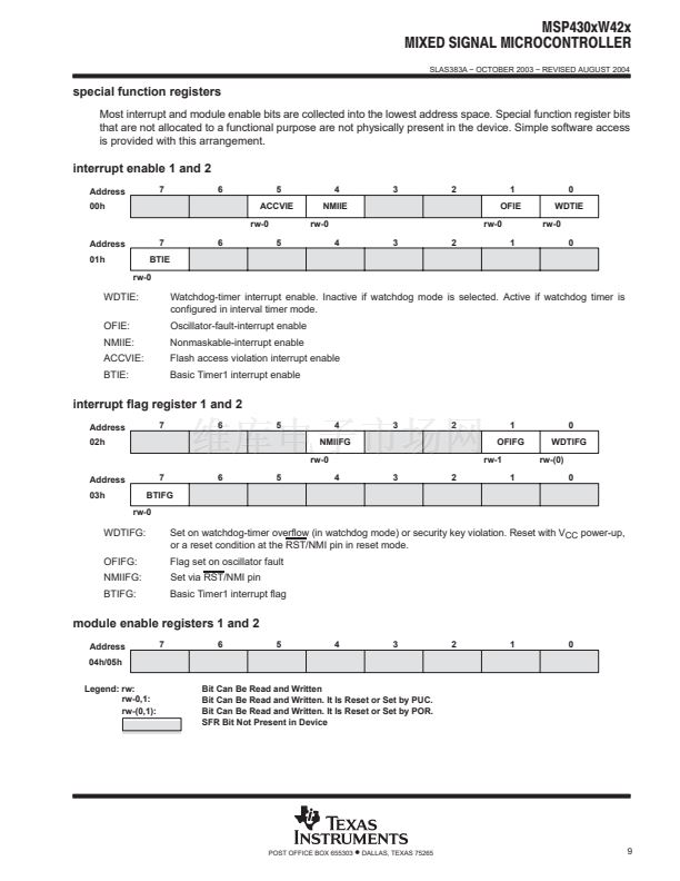
interrupt vector addresses
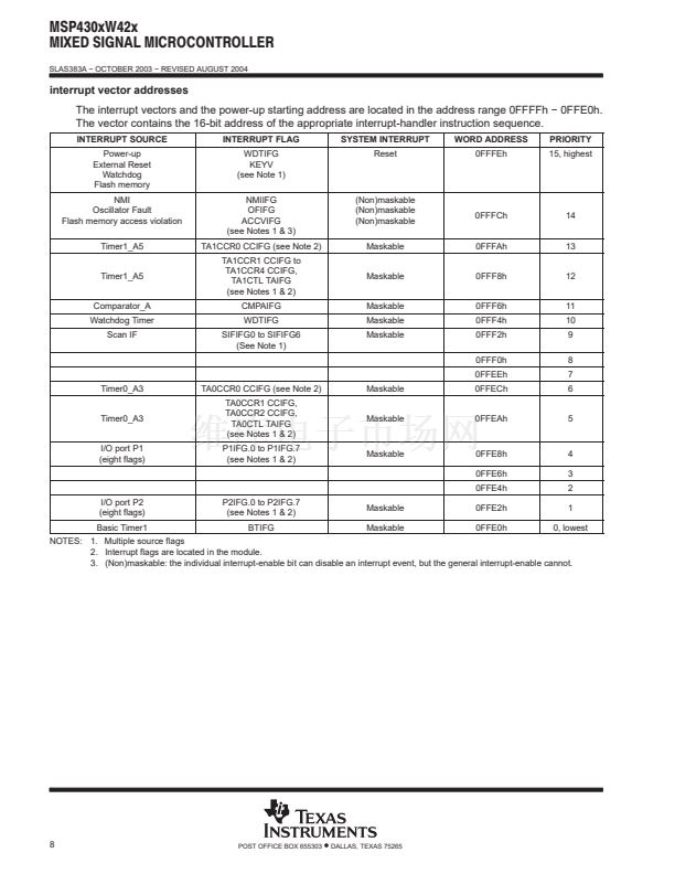
The interrupt vectors and the power-up starting address are located in the address range 0FFFFh 鈭?0FFE0h.
The vector contains the 16-bit address of the appropriate interrupt-handler instruction sequence.
INTERRUPT SOURCE
Power-up
External Reset
Watchdog
Flash memory
NMI
Oscillator Fault
Flash memory access violation
Timer1_A5
Timer1_A5
Comparator_A
Watchdog Timer
Scan IF
INTERRUPT FLAG
WDTIFG
KEYV
(see Note 1)
NMIIFG
OFIFG
ACCVIFG
(see Notes 1 & 3)
TA1CCR0 CCIFG (see Note 2)
TA1CCR1 CCIFG to
TA1CCR4 CCIFG,
TA1CTL TAIFG
(see Notes 1 & 2)
CMPAIFG
WDTIFG
SIFIFG0 to SIFIFG6
(See Note 1)
SYSTEM INTERRUPT
Reset
WORD ADDRESS
0FFFEh
PRIORITY
15, highest
(Non)maskable
(Non)maskable
(Non)maskable
Maskable
Maskable
Maskable
Maskable
Maskable
0FFFCh
0FFFAh
0FFF8h
0FFF6h
0FFF4h
0FFF2h
0FFF0h
0FFEEh
14
13
12
11
10
9
8
7
6
5
Timer0_A3
Timer0_A3
I/O port P1
(eight flags)
TA0CCR0 CCIFG (see Note 2)
TA0CCR1 CCIFG,
TA0CCR2 CCIFG,
TA0CTL TAIFG
(see Notes 1 & 2)
P1IFG.0 to P1IFG.7
(see Notes 1 & 2)
Maskable
Maskable
0FFECh
0FFEAh
Maskable
0FFE8h
0FFE6h
0FFE4h
4
3
2
1
0, lowest
I/O port P2
(eight flags)
Basic Timer1
P2IFG.0 to P2IFG.7
(see Notes 1 & 2)
BTIFG
Maskable
Maskable
0FFE2h
0FFE0h
NOTES: 1. Multiple source flags
2. Interrupt flags are located in the module.
3. (Non)maskable: the individual interrupt-enable bit can disable an interrupt event, but the general interrupt-enable cannot.
8
POST OFFICE BOX 655303
鈥?/div>
DALLAS, TEXAS 75265


 1
1
 2
2
 3
3
 4
4
 5
5
 6
6
 7
7
 8
8
 9
9
 10
10
 11
11
 12
12
 13
13
 14
14
 15
15
 16
16
 17
17
 18
18
 19
19
 20
20
 21
21
 22
22
 23
23
 24
24
 25
25
 26
26
 27
27
 28
28
 29
29
 30
30
 31
31
 32
32
 33
33
 34
34
 35
35
 36
36
 37
37
 38
38
 39
39
 40
40
 41
41
 42
42
 43
43
 44
44
 45
45
 46
46
 47
47
 48
48
 49
49
 50
50
 51
51
 52
52
 53
53
