100k鈩?/div>
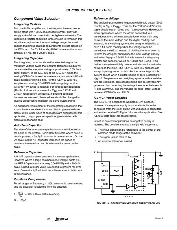
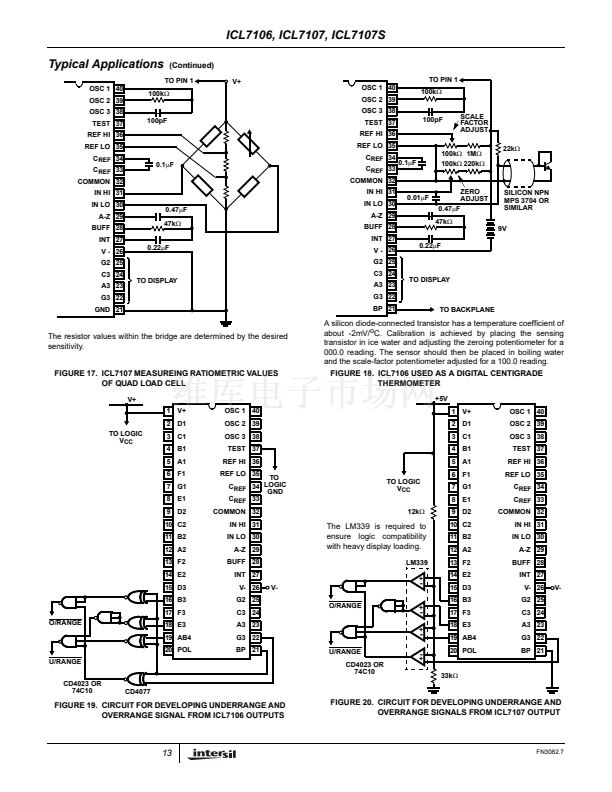
The resistor values within the bridge are determined by the desired
sensitivity.
FIGURE 17. ICL7107 MEASUREING RATIOMETRIC VALUES
OF QUAD LOAD CELL
V+
1 V+
2 D1
TO LOGIC
V
CC
3 C1
4 B1
5 A1
6 F1
7 G1
8 E1
9 D2
10 C2
11 B2
12 A2
13 F2
14 E2
15 D3
16 B3
17 F3
O/RANGE
18 E3
19 AB4
20 POL
U/RANGE
CD4023 OR
74C10
OSC 1 40
OSC 2 39
OSC 3 38
TEST 37
REF HI 36
REF LO 35
TO
C
REF
34 LOGIC
GND
C
REF
33
IN HI 31
IN LO 30
A-Z 29
BUFF 28
INT 27
V- 26
G2 25
C3 24
A3 23
G3 22
BP 21
V-
A silicon diode-connected transistor has a temperature coefficient of
about -2mV/
o
C. Calibration is achieved by placing the sensing
transistor in ice water and adjusting the zeroing potentiometer for a
000.0 reading. The sensor should then be placed in boiling water
and the scale-factor potentiometer adjusted for a 100.0 reading.
FIGURE 18. ICL7106 USED AS A DIGITAL CENTIGRADE
THERMOMETER
+5V
1 V+
2 D1
3 C1
4 B1
5 A1
6 F1
TO LOGIC
V
CC
12k鈩?/div>
7 G1
8 E1
9 D2
10 C2
11 B2
12 A2
13 F2
14 E2
15 D3
16 B3
+
OSC 1 40
OSC 2 39
OSC 3 38
TEST 37
REF HI 36
REF LO 35
C
REF
34
C
REF
33
COMMON 32
IN HI 31
IN LO 30
A-Z 29
BUFF 28
INT 27
V- 26
G2 25
C3 24
A3 23
G3 22
BP 21
V-
COMMON 32
The LM339 is required to
ensure logic compatibility
with heavy display loading.
LM339
+
-
-
-
-
O/RANGE
17 F3
18 E3
19 AB4
20 POL
+
U/RANGE
CD4023 OR
74C10
+
33k鈩?/div>
CD4077
FIGURE 19. CIRCUIT FOR DEVELOPING UNDERRANGE AND
OVERRANGE SIGNAL FROM ICL7106 OUTPUTS
FIGURE 20. CIRCUIT FOR DEVELOPING UNDERRANGE AND
OVERRANGE SIGNALS FROM ICL7107 OUTPUT
13
FN3082.7


 1
1
 2
2
 3
3
 4
4
 5
5
 6
6
 7
7
 8
8
 9
9
 10
10
 11
11
 12
12
 13
13
 14
14
 15
15
 16
16
