IDT 79RC32355
Name
JTAG_TMS
EJTAG_PCST[0]
Type I/O Type
I
O
STI
Description
JTAG Mode Select.
This input signal is decoded by the tap controller to control test operation. This signal requires an
external resistor, listed in Table 16.
Low Drive
PC trace status.
This bus gives the PC trace status information during EJTAG/ICE mode. EJTAG/ICE enable is selected
during reset using the boot configuration and overrides the selection of the Primary and Alternate functions. This signal
requires an external resistor, listed in Table 16.
Primary function: General Purpose I/O, GPIOP[10].
1st Alternate function: UART channel 1 data terminal ready, U1DTRN.
Low Drive
PC trace status.
This bus gives the PC trace status information during EJTAG/ICE mode. EJTAG/ICE enable is selected
during reset using the boot configuration and overrides the selection of the Primary and Alternate functions. This signal
requires an external resistor, listed in Table 16.
Primary function: General Purpose I/O, GPIOP[11]. At reset, this pin defaults to primary function GPIOP[11].
1st Alternate function: UART channel 1 data set ready, U1DSRN.
Low Drive
PC trace status.
This bus gives the PC trace status information during EJTAG/ICE mode. EJTAG/ICE enable is selected
during reset using the boot configuration and overrides the selection of the Primary and Alternate functions. This signal
requires an external resistor, listed in Table 16.
Primary function: General Purpose I/O, GPIOP[12].
1st Alternate function: UART channel 1 request to send, U1RTSN.
Low Drive
PC trace clock.
This is used to capture address and data during EJTAG/ICE mode. EJTAG/ICE enable is selected during
reset using the boot configuration and overrides the selection of the Primary and Alternate functions. This signal requires
an external resistor, listed in Table 16.
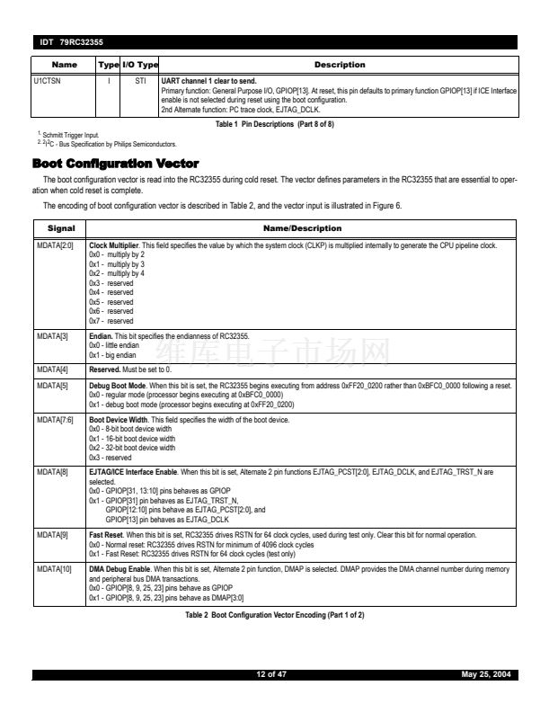
Primary function: General Purpose I/O, GPIOP[13].
1st Alternate function: UART channel 1 clear to send, U1CTSN.
STI
EJTAG Test Reset.
EJTAG_TRST_N is an active-low signal for asynchronous reset of only the EJTAG/ICE controller.
EJTAG_TRST_N requires an external pull-up on the board. EJTAG/ICE enable is selected during reset using the boot con-
figuration and overrides the selection of the Primary and Alternate functions. This signal requires an external resistor, listed
in Table 16.
Primary: General Purpose I/O, GPIOP[31]
1st Alternate function: DMA finished output, DMAFIN.
JTAG Test Reset.
JTAG_TRST_N is an active-low signal for asynchronous reset of only the JTAG boundary scan control-
ler. JTAG_TRST_N requires an external pull-down on the board that will hold the JTAG boundary scan controller in reset
when not in use if selected. JTAG reset enable is selected during reset using the boot configuration and overrides the
selection of the Primary and Alternate functions.
Primary function: General Purpose I/O, GPIOP[2].
1st Alternate function: UART channel 0 ring indicator, U0RIN.
EJTAG_PCST[1]
O
EJTAG_PCST[2]
O
EJTAG_DCLK
O
EJTAG_TRST_N
I
JTAG_TRST_N
I
STI
Debug
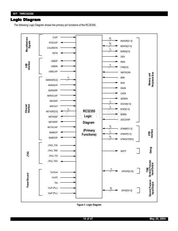
INSTP
CPUP
O
O
Low Drive
Instruction or Data Indicator.
This signal is driven high during CPU instruction fetches and low during CPU data transac-
tions on the memory and peripheral bus.
Low Drive
CPU or DMA Transaction Indicator.
This signal is driven high during CPU transactions and low during DMA transactions
on the memory and peripheral bus if CPU/DMA Transaction Indicator Enable is enabled. CPU/DMA Status mode enable is
selected during reset using the boot configuration and overrides the selection of the Primary and Alternate functions.
Primary function: General Purpose I/O, GPIOP[4].
1st Alternate function: UART channel 0 data terminal ready U0DTRN.
Low Drive
Active DMA channel code.
DMA debug enable is selected during reset using the boot configuration and overrides the
selection of the Primary and Alternate functions.
Primary function: General Purpose I/O, GPIOP[23].
1st Alternate function: TXADDR[1].
Low Drive
Active DMA channel code.
DMA debug enable is selected during reset using the boot configuration and overrides the
selection of the Primary and Alternate functions.
Primary function: General Purpose I/O, GPIOP[25].
1st Alternate function: RXADDR[1].
Table 1 Pin Descriptions (Part 6 of 8)
DMAP[0]
O
DMAP[1]
O
10 of 47
May 25, 2004


 1
1
 2
2
 3
3
 4
4
 5
5
 6
6
 7
7
 8
8
 9
9
 10
10
 11
11
 12
12
 13
13
 14
14
 15
15
 16
16
 17
17
 18
18
 19
19
 20
20
 21
21
 22
22
 23
23
 24
24
 25
25
 26
26
 27
27
 28
28
 29
29
 30
30
 31
31
 32
32
 33
33
 34
34
 35
35
 36
36
 37
37
 38
38
 39
39
 40
40
 41
41
 42
42
 43
43
 44
44
 45
45
 46
46
 47
47
