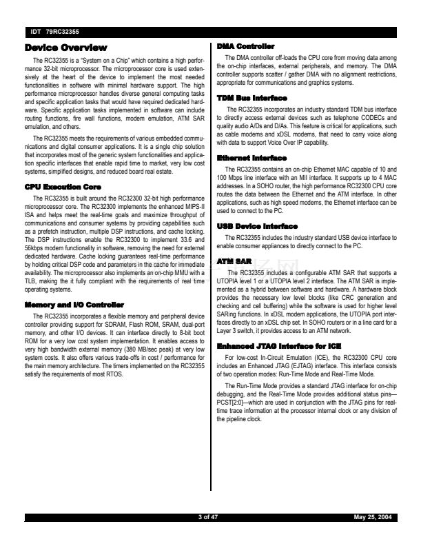
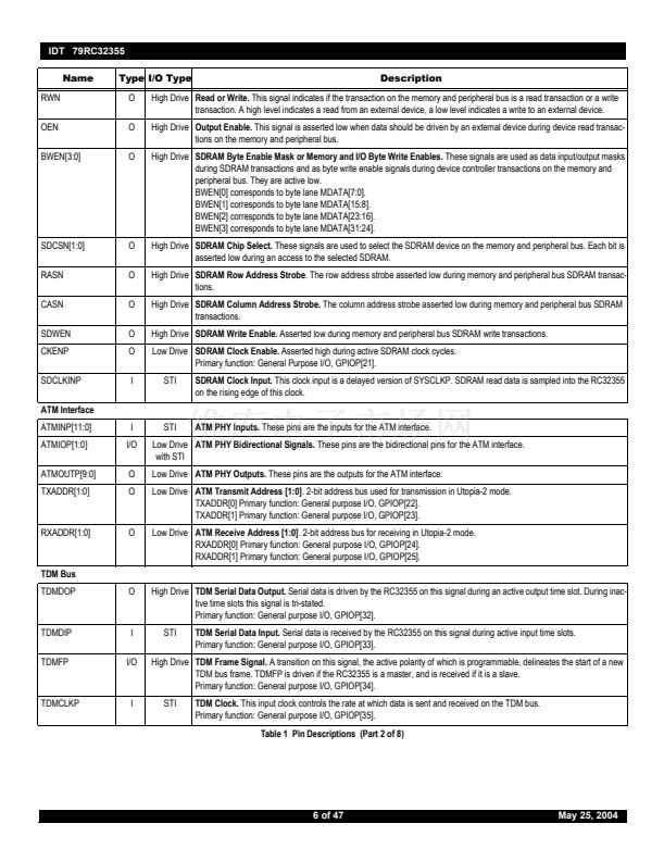
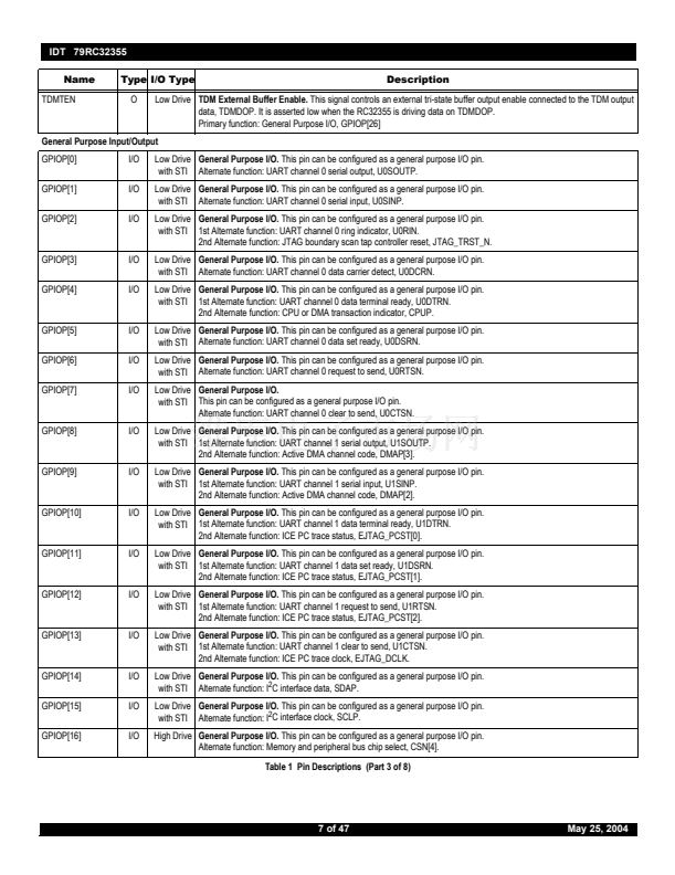
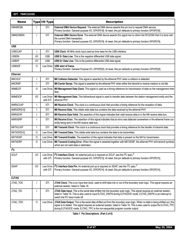
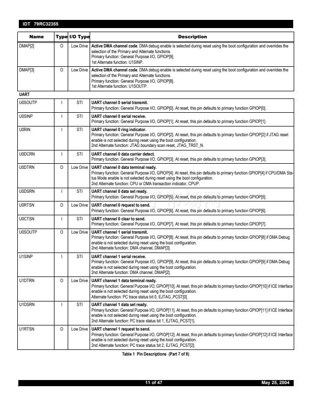
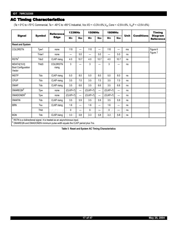
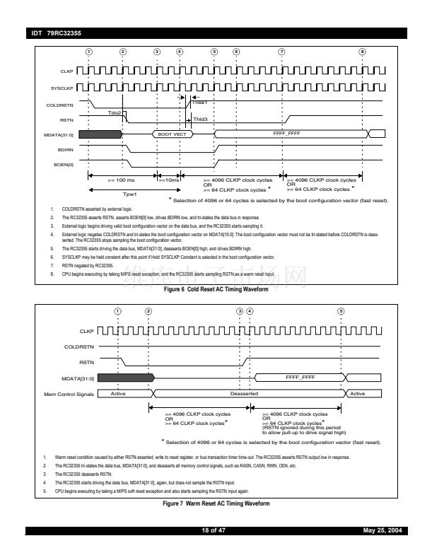
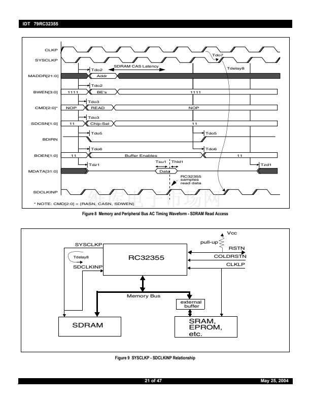
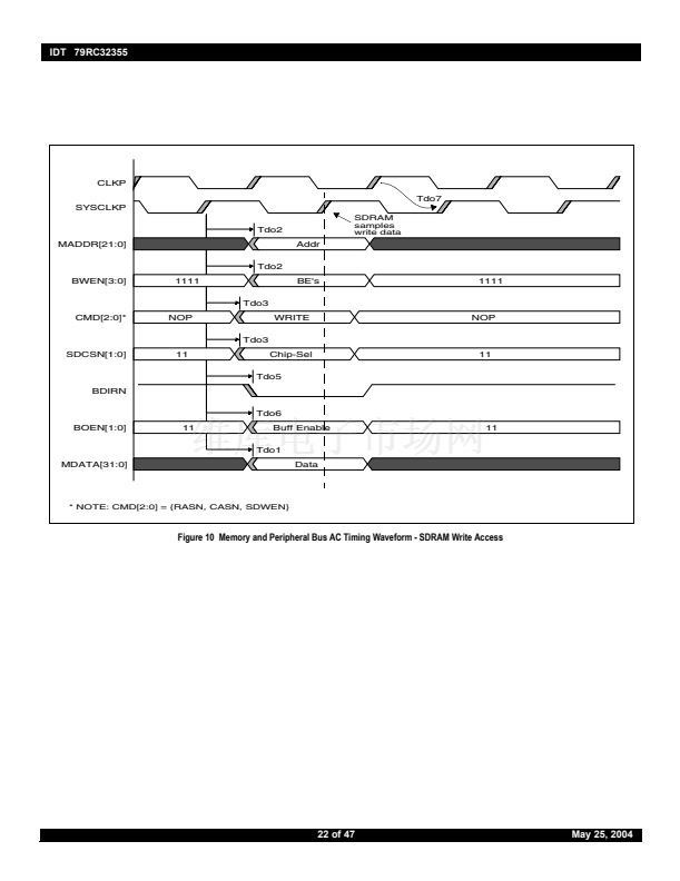
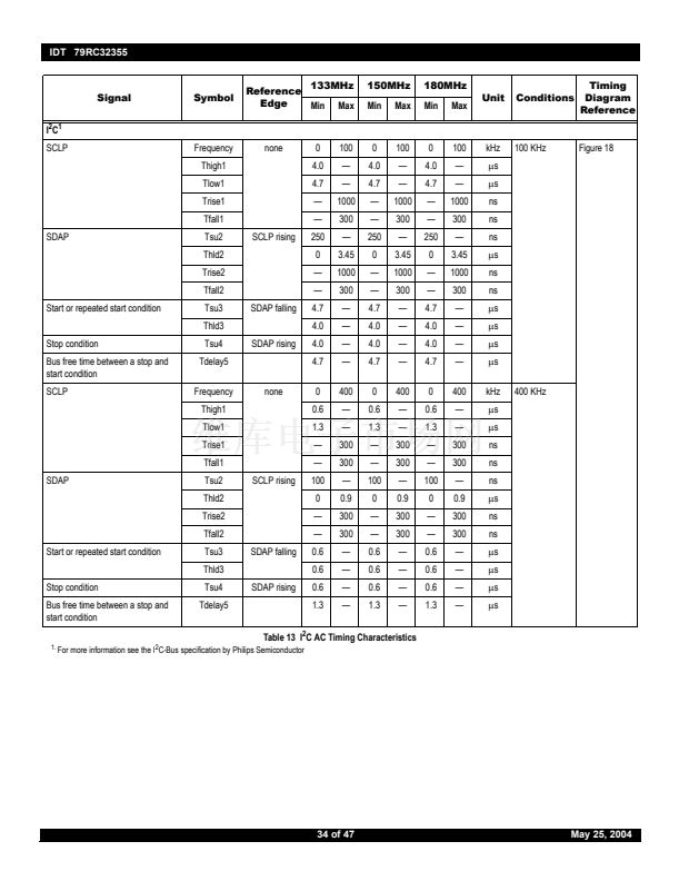
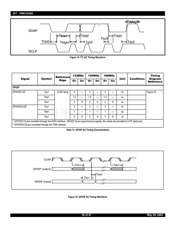
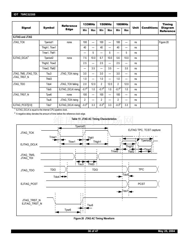
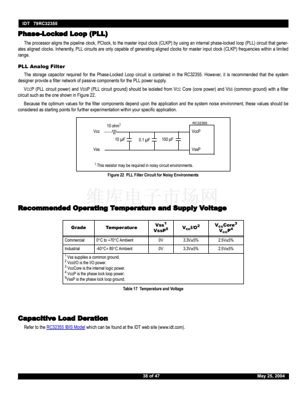
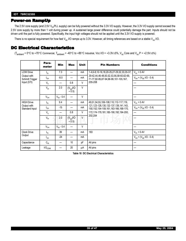
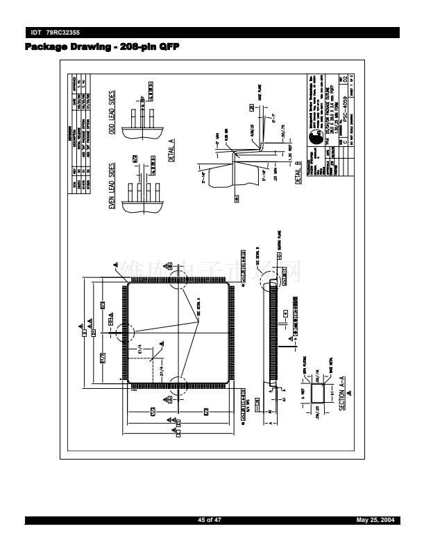
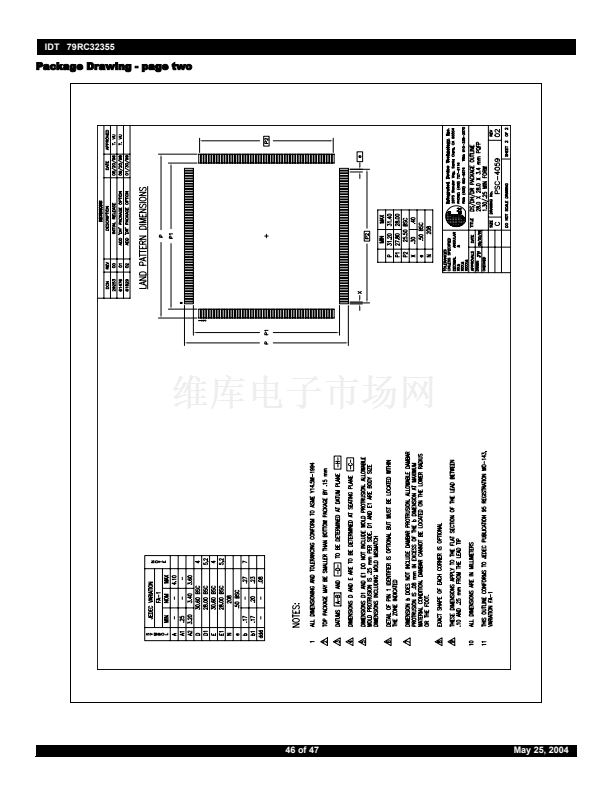
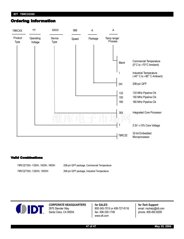
IDT 79RC32355
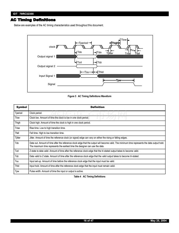
AC Timing Definitions
Below are examples of the AC timing characteristics used throughout this document.
Tlow
Tperiod
clock
Tdo
Output signal 1
Tzd
Output signal 2
Tsu
Input Signal 1
Tpw
Signal
Thld
Tdz
Tdo
Tjitter
Trise
Tfall
Thigh
Figure 5 AC Timing Definitions Waveform
Symbol
Tperiod
Tlow
Thigh
Trise
Tfall
Tjitter
Tdo
Tzd
Tdz
Tsu
Thld
Tpw
Clock period.
Clock low. Amount of time the clock is low in one clock period.
Clock high. Amount of time the clock is high in one clock period.
Rise time. Low to high transition time.
Fall time. High to low transition time.
Definition
Jitter. Amount of time the reference clock (or signal) edge can vary on either the rising or falling edges.
Data out. Amount of time after the reference clock edge that the output will become valid. The minimum time represents the data output hold.
The maximum time represents the earliest time the designer can use the data.
Z state to data valid. Amount of time after the reference clock edge that the tri-stated output takes to become valid.
Data valid to Z state. Amount of time after the reference clock edge that the valid output takes to become tri-stated.
Input set-up. Amount of time before the reference clock edge that the input must be valid.
Input hold. Amount of time after the reference clock edge that the input must remain valid.
Pulse width. Amount of time the input or output is active.
Table 4 AC Timing Definitions
16 of 47
May 25, 2004


 1
1
 2
2
 3
3
 4
4
 5
5
 6
6
 7
7
 8
8
 9
9
 10
10
 11
11
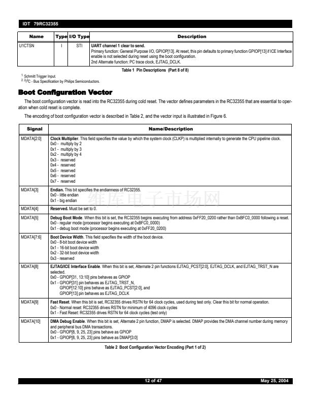 12
12
 13
13
 14
14
 15
15
 16
16
 17
17
 18
18
 19
19
 20
20
 21
21
 22
22
 23
23
 24
24
 25
25
 26
26
 27
27
 28
28
 29
29
 30
30
 31
31
 32
32
 33
33
 34
34
 35
35
 36
36
 37
37
 38
38
 39
39
 40
40
 41
41
 42
42
 43
43
 44
44
 45
45
 46
46
 47
47
