IDT 79RC32355
Phase-Locked Loop (PLL)
The processor aligns the pipeline clock, PClock, to the master input clock (CLKP) by using an internal phase-locked loop (PLL) circuit that gener-
ates aligned clocks. Inherently, PLL circuits are only capable of generating aligned clocks for master input clock (CLKP) frequencies within a limited
range.
PLL Analog Filter
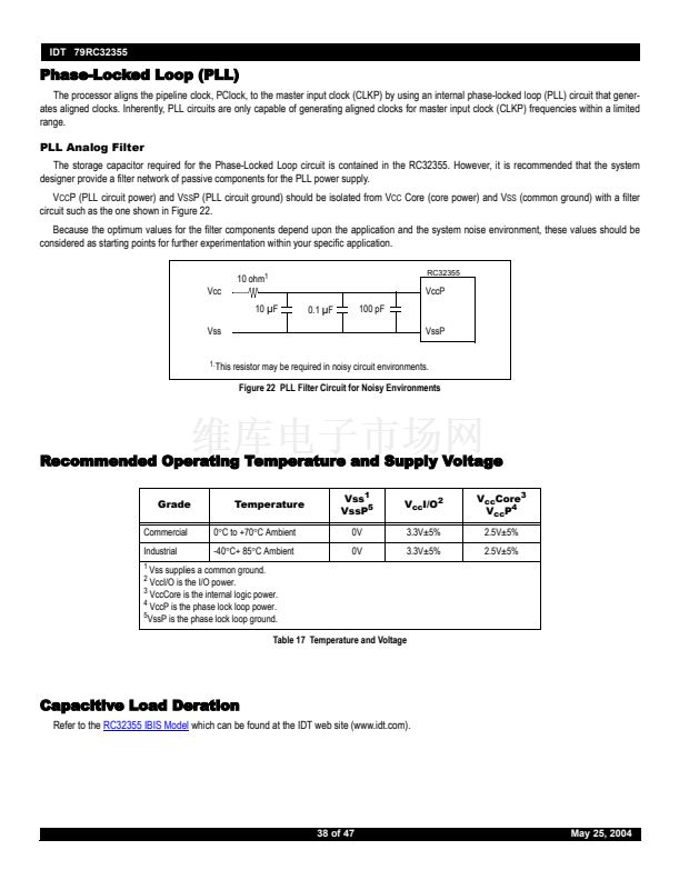
The storage capacitor required for the Phase-Locked Loop circuit is contained in the RC32355. However, it is recommended that the system
designer provide a filter network of passive components for the PLL power supply.
V
CC
P (PLL circuit power) and V
SS
P (PLL circuit ground) should be isolated from V
CC
Core (core power) and V
SS
(common ground) with a filter
circuit such as the one shown in Figure 22.
Because the optimum values for the filter components depend upon the application and the system noise environment, these values should be
considered as starting points for further experimentation within your specific application.
10 ohm
1
Vcc
10
碌
F
Vss
0.1
碌
F
100 pF
VssP
RC32355
VccP
1.
This resistor may be required in noisy circuit environments.
Figure 22 PLL Filter Circuit for Noisy Environments
Recommended Operating Temperature and Supply Voltage
Grade
Commercial
Industrial
1
Temperature
0掳C to +70掳C Ambient
-40掳C+ 85掳C Ambient
Vss
1
VssP
5
0V
0V
V
cc
I/O
2
3.3V卤5%
3.3V卤5%
V
cc
Core
3
V
cc
P
4
2.5V卤5%
2.5V卤5%
2
VccI/O is the I/O power.
Vss supplies a common ground.
3
VccCore is the internal logic power.
4
VccP is the phase lock loop power.
5
VssP is the phase lock loop ground.
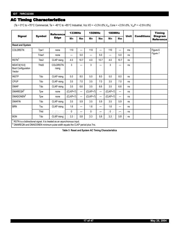
Table 17 Temperature and Voltage
Capacitive Load Deration
Refer to the
RC32355 IBIS Model
which can be found at the IDT web site (www.idt.com).
38 of 47
May 25, 2004


 1
1
 2
2
 3
3
 4
4
 5
5
 6
6
 7
7
 8
8
 9
9
 10
10
 11
11
 12
12
 13
13
 14
14
 15
15
 16
16
 17
17
 18
18
 19
19
 20
20
 21
21
 22
22
 23
23
 24
24
 25
25
 26
26
 27
27
 28
28
 29
29
 30
30
 31
31
 32
32
 33
33
 34
34
 35
35
 36
36
 37
37
 38
38
 39
39
 40
40
 41
41
 42
42
 43
43
 44
44
 45
45
 46
46
 47
47
