256-Mbit J3 (x8/x16)
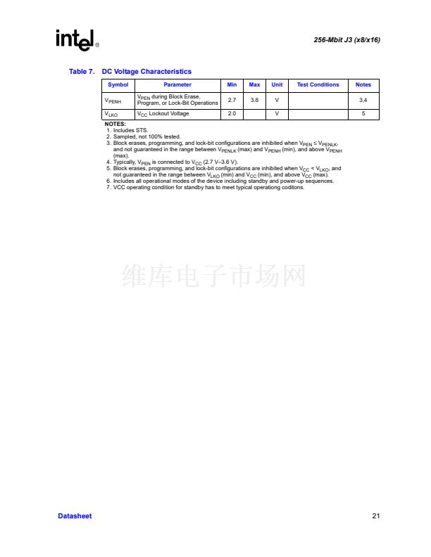
Table 7.
DC Voltage Characteristics
Symbol
V
PENH
V
LKO
Parameter
V
PEN
during Block Erase,
Program, or Lock-Bit Operations
V
CC
Lockout Voltage
Min
2.7
2.0
Max
3.6
Unit
V
V
Test Conditions
Notes
3,4
5
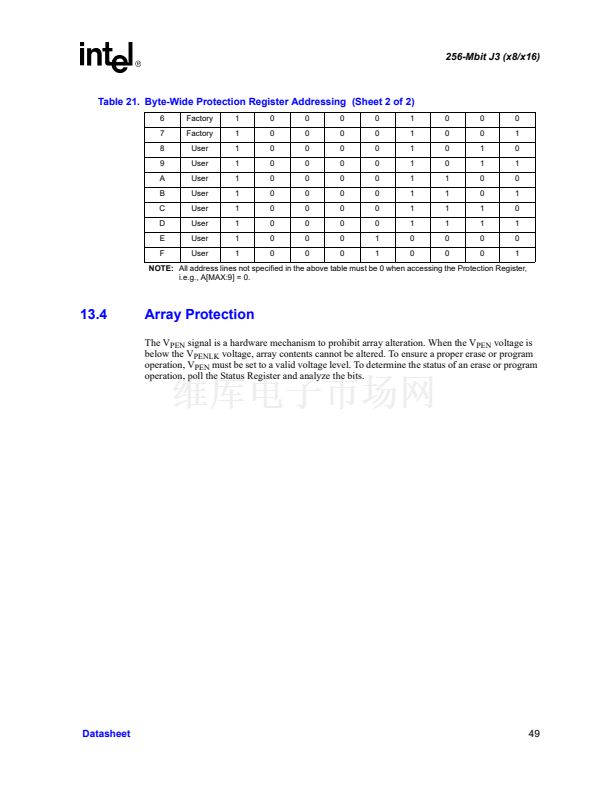
NOTES:
1. Includes STS.
2. Sampled, not 100% tested.
3. Block erases, programming, and lock-bit configurations are inhibited when V
PEN
鈮?/div>
V
PENLK
,
and not guaranteed in the range between V
PENLK
(max) and V
PENH
(min), and above V
PENH
(max).
4. Typically, V
PEN
is connected to V
CC
(2.7 V鈥?.6 V).
5. Block erases, programming, and lock-bit configurations are inhibited when V
CC
< V
LKO
, and
not guaranteed in the range between V
LKO
(min) and V
CC
(min), and above V
CC
(max).
6. Includes all operational modes of the device including standby and power-up sequences.
7. VCC operating condition for standby has to meet typical operationg coditons.
Datasheet
21


 1
1
 2
2
 3
3
 4
4
 5
5
 6
6
 7
7
 8
8
 9
9
 10
10
 11
11
 12
12
 13
13
 14
14
 15
15
 16
16
 17
17
 18
18
 19
19
 20
20
 21
21
 22
22
 23
23
 24
24
 25
25
 26
26
 27
27
 28
28
 29
29
 30
30
 31
31
 32
32
 33
33
 34
34
 35
35
 36
36
 37
37
 38
38
 39
39
 40
40
 41
41
 42
42
 43
43
 44
44
 45
45
 46
46
 47
47
 48
48
 49
49
 50
50
 51
51
 52
52
 53
53
 54
54
 55
55
 56
56
 57
57
 58
58
 59
59
 60
60
 61
61
 62
62
 63
63
 64
64
 65
65
 66
66
 67
67
 68
68
 69
69
 70
70
 71
71
 72
72
