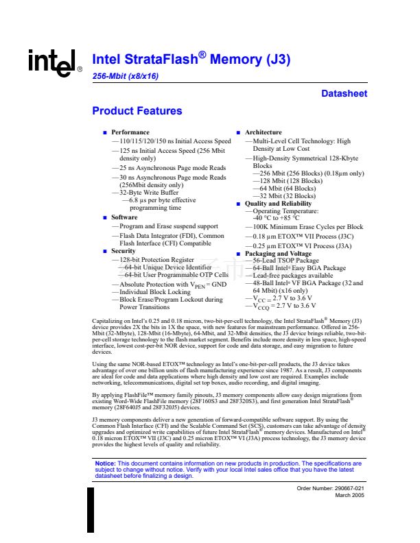
256-Mbit J3 (x8/x16)
13.0
Security Modes
This device offers both hardware and software security features. Block lock operations, PRs, and
VPEN allow the user to implement various levels of data protection. The following section
describes security features in detail.
Other security features are available that are not described in this datasheet. Please contact your
local Intel Field Representative for more information.
13.1
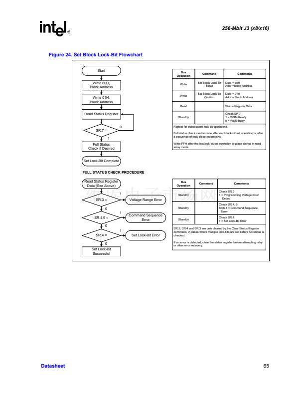
Set Block Lock-Bit
A flexible block locking scheme is enabled via block lock-bits. The block lock-bits gate program
and erase operations. Individual block lock-bits can be set using the Set Block Lock-Bit command.
This command is invalid while the WSM is running or the device is suspended.
Set block lock-bit commands are executed by a two-cycle sequence. The set block setup along with
appropriate block address is followed by either the set block lock-bit confirm (and an address
within the block to be locked). The WSM then controls the set lock-bit algorithm. After the
sequence is written, the device automatically outputs Status Register data when read (see
Figure 24
on page 65).
The CPU can detect the completion of the set lock-bit event by analyzing the STS
signal output or SR.7.
When the set lock-bit operation is complete, SR.4 should be checked. If an error is detected, the
Status Register should be cleared. The CUI will remain in Read Status Register mode until a new
command is issued.
This two-step sequence of setup followed by execution ensures that lock-bits are not accidentally
set. An invalid Set Block Lock-Bit command will result in SR.4 and SR.5 being set. Also, reliable
operations occur only when V
CC
and V
PEN
are valid. With V
PEN
鈮?/div>
V
PENLK
, lock-bit contents are
protected against alteration.
13.2
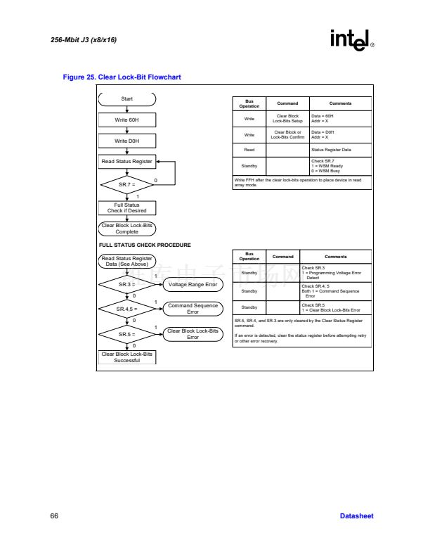
Clear Block Lock-Bits
All set block lock-bits are cleared in parallel via the Clear Block Lock-Bits command. Block lock-
bits can be cleared using only the Clear Block Lock-Bits command. This command is invalid while
the WSM is running or the device is suspended.
Clear block lock-bits command is executed by a two-cycle sequence. A clear block lock-bits setup
is first written. The device automatically outputs Status Register data when read (see
Figure 25 on
page 66).
The CPU can detect completion of the clear block lock-bits event by analyzing the STS
signal output or SR.7.
When the operation is complete, SR.5 should be checked. If a clear block lock-bit error is detected,
the Status Register should be cleared. The CUI will remain in Read Status Register mode until
another command is issued.
46
Datasheet


 1
1
 2
2
 3
3
 4
4
 5
5
 6
6
 7
7
 8
8
 9
9
 10
10
 11
11
 12
12
 13
13
 14
14
 15
15
 16
16
 17
17
 18
18
 19
19
 20
20
 21
21
 22
22
 23
23
 24
24
 25
25
 26
26
 27
27
 28
28
 29
29
 30
30
 31
31
 32
32
 33
33
 34
34
 35
35
 36
36
 37
37
 38
38
 39
39
 40
40
 41
41
 42
42
 43
43
 44
44
 45
45
 46
46
 47
47
 48
48
 49
49
 50
50
 51
51
 52
52
 53
53
 54
54
 55
55
 56
56
 57
57
 58
58
 59
59
 60
60
 61
61
 62
62
 63
63
 64
64
 65
65
 66
66
 67
67
 68
68
 69
69
 70
70
 71
71
 72
72
