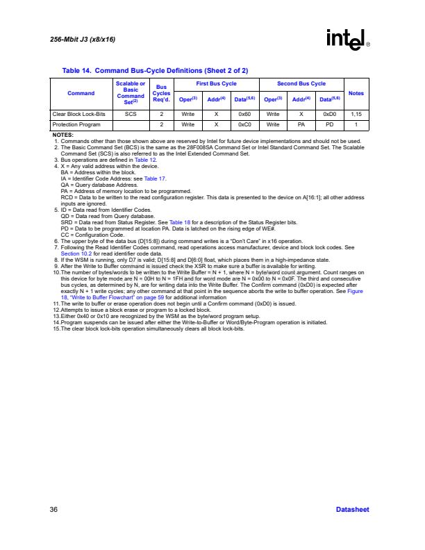
256-Mbit J3 (x8/x16)
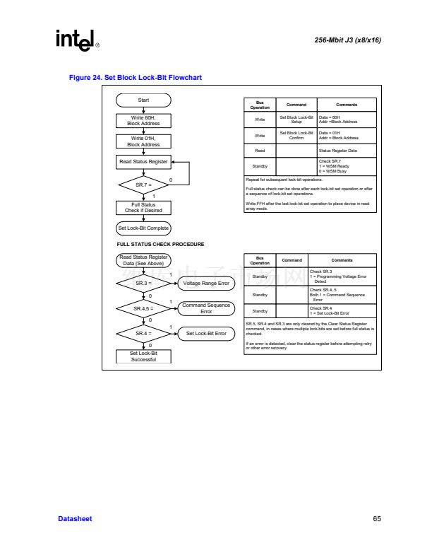
Figure 24. Set Block Lock-Bit Flowchart
Start
Bus
Operation
Write
Command
Set Block Lock-Bit
Setup
Set Block Lock-Bit
Confirm
Comments
Data = 60H
Addr =Block Address
Data = 01H
Addr = Block Address
Status Register Data
Check SR.7
1 = WSM Ready
0 = WSM Busy
Write 60H,
Block Address
Write 01H,
Block Address
Write
Read
Read Status Register
Standby
SR.7 =
1
Full Status
Check if Desired
0
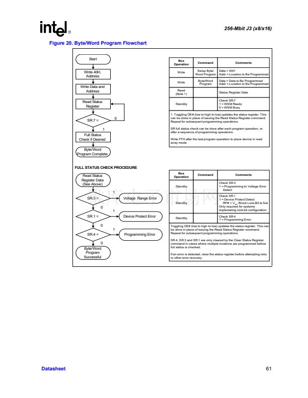
Repeat for subsequent lock-bit operations.
Full status check can be done after each lock-bit set operation or after
a sequence of lock-bit set operations.
Write FFH after the last lock-bit set operation to place device in read
array mode.
Set Lock-Bit Complete
FULL STATUS CHECK PROCEDURE
Read Status Register
Data (See Above)
1
SR.3 =
0
1
SR.4,5 =
0
1
SR.4 =
0
Set Lock-Bit
Successful
Set Lock-Bit Error
Command Sequence
Error
Voltage Range Error
Standby
Bus
Operation
Standby
Command
Comments
Check SR.3
1 = Programming Voltage Error
Detect
Check SR.4, 5
Both 1 = Command Sequence
Error
Check SR.4
1 = Set Lock-Bit Error
Standby
SR.5, SR.4 and SR.3 are only cleared by the Clear Status Register
command, in cases where multiple lock-bits are set before full status is
checked.
If an error is detected, clear the status register before attempting retry
or other error recovery.
Datasheet
65


 1
1
 2
2
 3
3
 4
4
 5
5
 6
6
 7
7
 8
8
 9
9
 10
10
 11
11
 12
12
 13
13
 14
14
 15
15
 16
16
 17
17
 18
18
 19
19
 20
20
 21
21
 22
22
 23
23
 24
24
 25
25
 26
26
 27
27
 28
28
 29
29
 30
30
 31
31
 32
32
 33
33
 34
34
 35
35
 36
36
 37
37
 38
38
 39
39
 40
40
 41
41
 42
42
 43
43
 44
44
 45
45
 46
46
 47
47
 48
48
 49
49
 50
50
 51
51
 52
52
 53
53
 54
54
 55
55
 56
56
 57
57
 58
58
 59
59
 60
60
 61
61
 62
62
 63
63
 64
64
 65
65
 66
66
 67
67
 68
68
 69
69
 70
70
 71
71
 72
72
