TMS320VC5416
Fixed-Point Digital Signal Processor
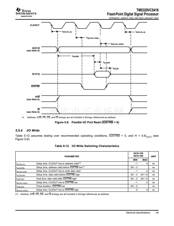
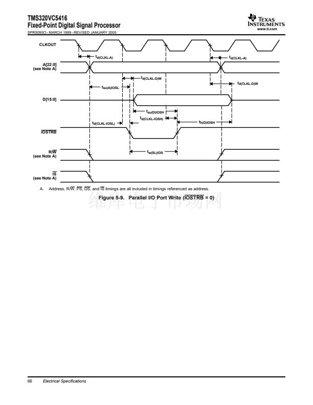
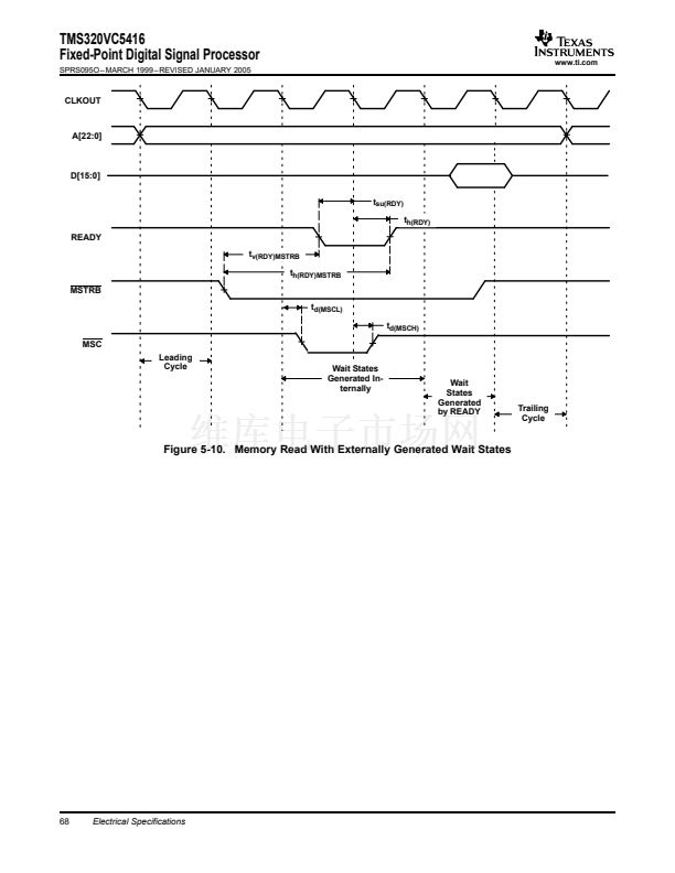
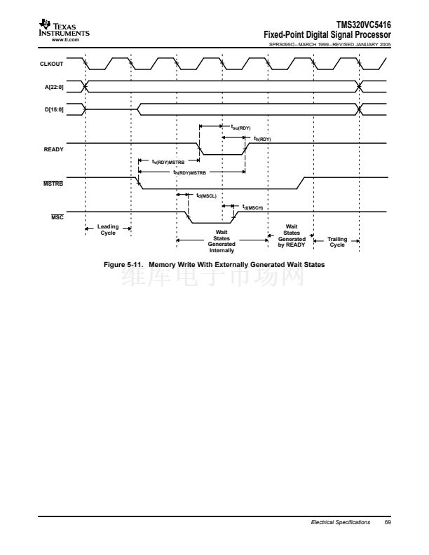
SPRS095O 鈥?MARCH 1999 鈥?REVISED JANUARY 2005
www.ti.com
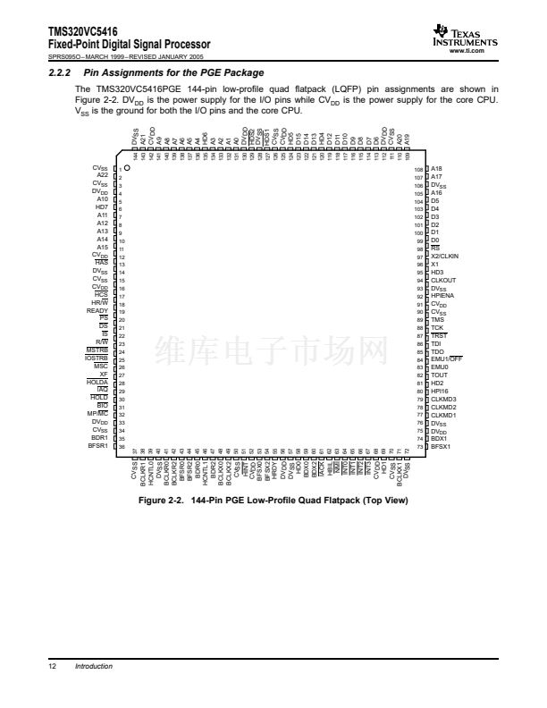
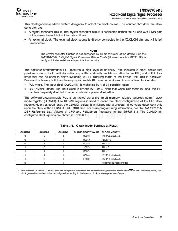
5.3.3
Internal Oscillator With External Crystal
The internal oscillator is enabled by selecting the appropriate clock mode at reset (this is de-
vice-dependent; see Section Section 3.10) and connecting a crystal or ceramic resonator across X1 and
X2/CLKIN. The CPU clock frequency is one-half, one-fourth, or a multiple of the oscillator frequency. The
multiply ratio is determined by the bit settings in the CLKMD register.
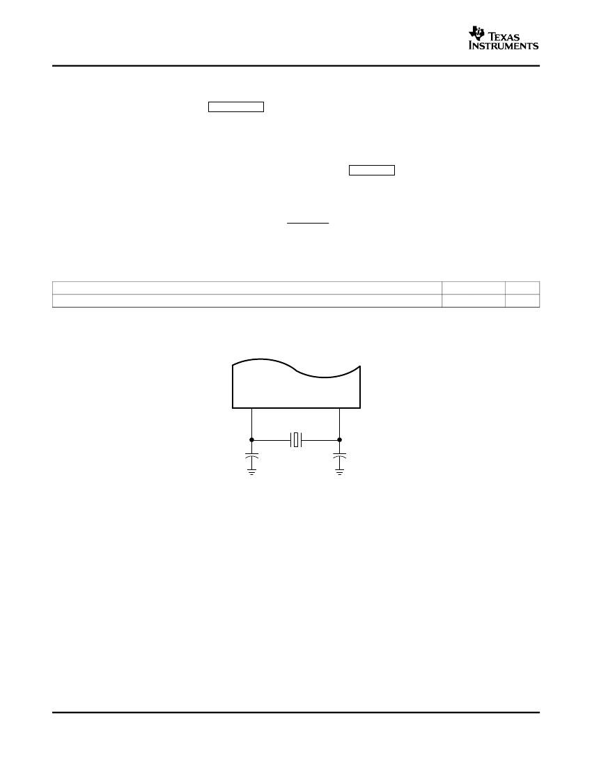
The crystal should be in fundamental-mode operation, and parallel resonant, with an effective series
resistance of 30
鈩?/div>
maximum and power dissipation of 1 mW. The connection of the required circuit,
consisting of the crystal and two load capacitors, is shown in Figure 5-2. The load capacitors, C
1
and C
2
,
should be chosen such that the equation below is satisfied. C
L
(recommended value of 10 pF) in the
equation is the load specified for the crystal.
C
L
+
C
1
C
2
(C
1
)
C
2
)
Table 5-1. Input Clock Frequency Characteristics
MIN
f
x
(1)
(2)
Input clock frequency
10
(1)
MAX
20
(2)
Unit
MHz
This device utilizes a fully static design and therefore can operate with t
c(CI)
approaching
鈭?
The device is characterized at frequencies
approaching 0 Hz
It is recommended that the PLL multiply by N clocking option be used for maximum frequency operation.
X1
Crystal
X2/CLKIN
C1
C2
Figure 5-2. Internal Divide-By-Two Clock Option With External Crystal
56
Electrical Specifications


 1
1
 2
2
 3
3
 4
4
 5
5
 6
6
 7
7
 8
8
 9
9
 10
10
 11
11
 12
12
 13
13
 14
14
 15
15
 16
16
 17
17
 18
18
 19
19
 20
20
 21
21
 22
22
 23
23
 24
24
 25
25
 26
26
 27
27
 28
28
 29
29
 30
30
 31
31
 32
32
 33
33
 34
34
 35
35
 36
36
 37
37
 38
38
 39
39
 40
40
 41
41
 42
42
 43
43
 44
44
 45
45
 46
46
 47
47
 48
48
 49
49
 50
50
 51
51
 52
52
 53
53
 54
54
 55
55
 56
56
 57
57
 58
58
 59
59
 60
60
 61
61
 62
62
 63
63
 64
64
 65
65
 66
66
 67
67
 68
68
 69
69
 70
70
 71
71
 72
72
 73
73
 74
74
 75
75
 76
76
 77
77
 78
78
 79
79
 80
80
 81
81
 82
82
 83
83
 84
84
 85
85
 86
86
 87
87
 88
88
 89
89
 90
90
 91
91
 92
92
 93
93
 94
94
 95
95
 96
96
 97
97
 98
98
