MAX6640AEE Datasheet

  • MAX6640AEE

  • 2-Channel Temperature Monitor with Dual Automatic PWM Fan-Sp...

  • 722.10KB

  • 22页

  • MAXIM   MAXIM

扫码查看芯片数据手册

上传产品规格书

PDF预览

2-Channel Temperature Monitor with Dual
Automatic PWM Fan-Speed Controller
MAX6640
Table 7. Temperature Step Size
D[3:2]
00
01
10
11
FAN CONTROL TEMPERATURE
STEP SIZE (掳C)
1
2
4
8
Table 8. Fan PWM Frequency
D[1:0]
00
01
10
11
LOW FREQUENCY (Hz)
20
33.33
50
100
Fan 1 and 2 Configuration 2b (12h and 16h)
The following registers select the tachometer step sizes
and number of steps for step-size A to step-size B
slope changes (see Figure 1):
鈥?/div>
D[7:4]: RPM (Tachometer) Step Size B.
Selects
number of tachometer counts the target value
decreases for each temperature step increase after
the number of steps selected by D[3:0]. Value = n +
1 (1 through 16) where n is the value of D[7:4].
鈥?/div>
D[3:0]:
Selects the number of temperature/tachome-
ter steps above the fan-start temperature at which
step-size B begins.
Fan 1 and Fan 2 Configuration 3 (13h and 17h)
The following registers control fan spin-up, PWM output
frequency, pulse stretching, and
THERM
to fan full-
speed enable:
鈥?/div>
D7: Fan Spin-Up Disable.
Set to zero to enable fan
spin-up. Whenever the fan starts up from zero drive,
it is driven with 100% duty cycle for 2s to ensure that
it starts. Set to 1 to disable the spin-up function.
鈥?/div>
D6:
THERM
to Full-Speed Enable.
When this bit is
1,
THERM
going low (either by being pulled low
externally or by the measured temperature exceed-
ing the THERM limit) forces the fan to full speed. In
all modes, this happens at the rate determined by
the rate-of-change selection. When
THERM
is
deasserted (even if fan has not reached full speed),
the speed falls at the selected rate-of-change to the
target speed.
鈥?/div>
D5: Disable Pulse Stretching.
Pulse stretching is
enabled when this bit is set to zero. When modulat-
ing the fan鈥檚 power supply with the PWM signal, the
PWM pulses are periodically stretched to keep the
tachometer signal available for one full revolution.
Setting this bit to 1 disables pulse stretching. The
MAX6640 still measures the fan speed but does not
stretch the pulses for measurements, so the fan鈥檚
power supply must not be pulse modulated.
鈥?/div>
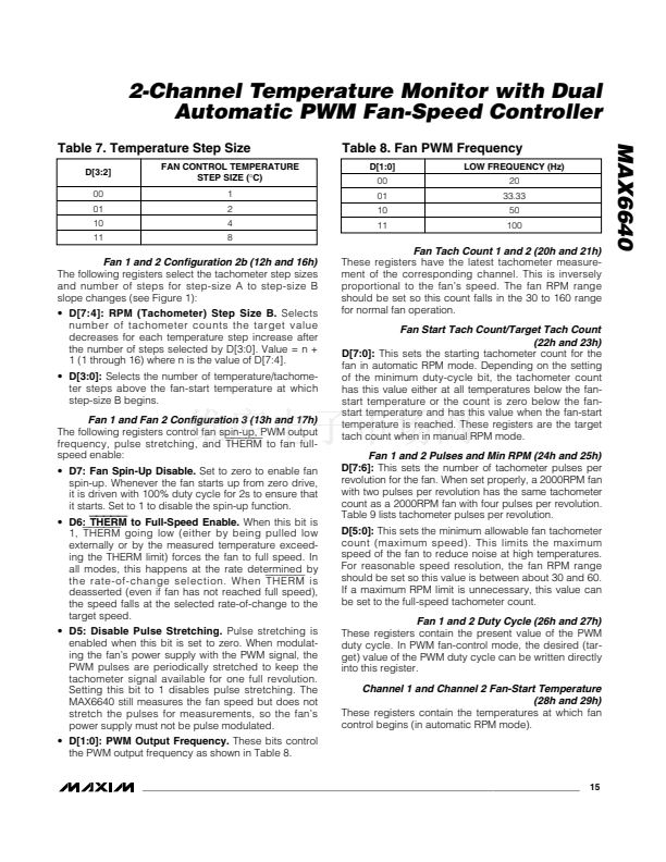
D[1:0]: PWM Output Frequency.
These bits control
the PWM output frequency as shown in Table 8.
Fan Tach Count 1 and 2 (20h and 21h)
These registers have the latest tachometer measure-
ment of the corresponding channel. This is inversely
proportional to the fan鈥檚 speed. The fan RPM range
should be set so this count falls in the 30 to 160 range
for normal fan operation.
Fan Start Tach Count/Target Tach Count
(22h and 23h)
D[7:0]:
This sets the starting tachometer count for the
fan in automatic RPM mode. Depending on the setting
of the minimum duty-cycle bit, the tachometer count
has this value either at all temperatures below the fan-
start temperature or the count is zero below the fan-
start temperature and has this value when the fan-start
temperature is reached. These registers are the target
tach count when in manual RPM mode.
Fan 1 and 2 Pulses and Min RPM (24h and 25h)
D[7:6]:
This sets the number of tachometer pulses per
revolution for the fan. When set properly, a 2000RPM fan
with two pulses per revolution has the same tachometer
count as a 2000RPM fan with four pulses per revolution.
Table 9 lists tachometer pulses per revolution.
D[5:0]:
This sets the minimum allowable fan tachometer
count (maximum speed). This limits the maximum
speed of the fan to reduce noise at high temperatures.
For reasonable speed resolution, the fan RPM range
should be set so this value is between about 30 and 60.
If a maximum RPM limit is unnecessary, this value can
be set to the full-speed tachometer count.
Fan 1 and 2 Duty Cycle (26h and 27h)
These registers contain the present value of the PWM
duty cycle. In PWM fan-control mode, the desired (tar-
get) value of the PWM duty cycle can be written directly
into this register.
Channel 1 and Channel 2 Fan-Start Temperature
(28h and 29h)
These registers contain the temperatures at which fan
control begins (in automatic RPM mode).
______________________________________________________________________________________
15

MAX6640AEE相关型号PDF文件下载

  • 型号
    版本
    描述
    厂商
    下载
  • 英文版
    AC To DC Regulator
    MAXIM
  • 英文版
    AC To DC Regulator
    MAXIM [Max...
  • 英文版
    AC To DC Regulator
    MAXIM
  • 英文版
    AC To DC Regulator
    MAXIM [Max...
  • 英文版
    AC To DC Regulator
    MAXIM
  • 英文版
    AC To DC Regulator
    MAXIM [Max...
  • 英文版
    5V/3.3V or Adjustable, Low-Dropout, Low IQ, 500mA Linear Reg...
    MAXIM
  • 英文版
    5V/3.3V or Adjustable, Low-Dropout, Low IQ, 500mA Linear Reg...
    MAXIM [Max...
  • 英文版
    5V/3.3V or Adjustable, Low-Dropout, Low IQ, 500mA Linear Reg...
    MAXIM
  • 英文版
    5V/3.3V or Adjustable, Low-Dropout, Low IQ, 500mA Linear Reg...
    MAXIM [Max...
  • 英文版
    Low-Profile, 5V/12V or Adjustable, Step-Up DC-DC Converters ...
    MAXIM
  • 英文版
    Low-Profile, 5V/12V or Adjustable, Step-Up DC-DC Converters ...
    MAXIM [Max...
  • 英文版
    Low-Profile, 5V/12V or Adjustable, Step-Up DC-DC Converters ...
    MAXIM
  • 英文版
    Low-Profile, 5V/12V or Adjustable, Step-Up DC-DC Converters ...
    MAXIM [Max...
  • 英文版
    5V or Adjustable, Low-Voltage, Step-Up DC-DC Controller
    MAXIM
  • 英文版
    5V or Adjustable, Low-Voltage, Step-Up DC-DC Controller
    MAXIM [Max...
  • 英文版
    AC-to-DC Regulator (110/220VAC to 5.0VDC)
    Maixm
  • 英文版
    AC-to-DC Regulator (110/220VAC to 5.0VDC)
    Maixm
  • 英文版
    AC-to-DC Regulator (110/220VAC to 5.0VDC)
    Maixm
  • 英文版
    Dual-Slot PCMCIA Analog Power Controllers
    MAXIM

扫码下载APP,
一键连接广大的电子世界。

在线人工客服

买家服务:
卖家服务:

0571-85317607

客服在线时间周一至周五
9:00-17:30

关注官方微信号,
第一时间获取资讯。

建议反馈

联系人:

联系方式:

按住滑块,拖拽到最右边
>>
感谢您向阿库提出的宝贵意见,您的参与是维库提升服务的动力!意见一经采纳,将有感恩红包奉上哦!