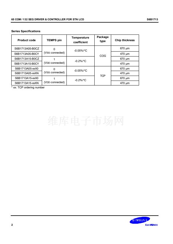
S6B1713
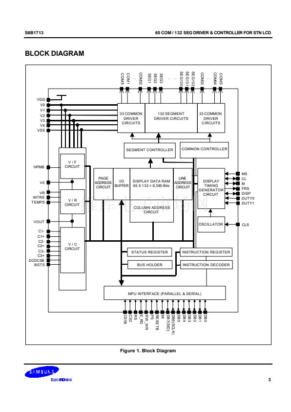
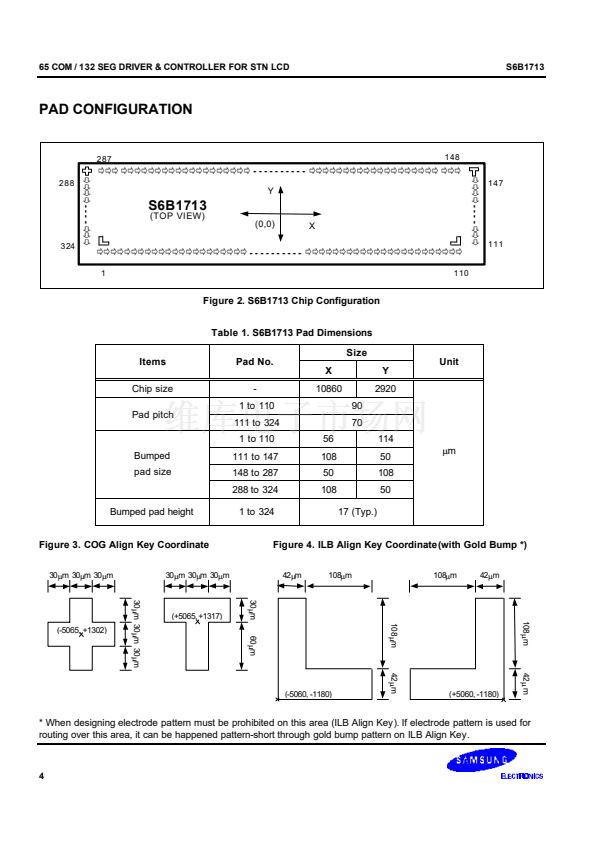
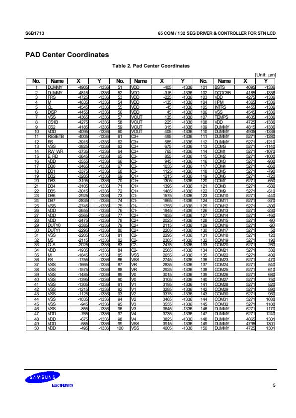
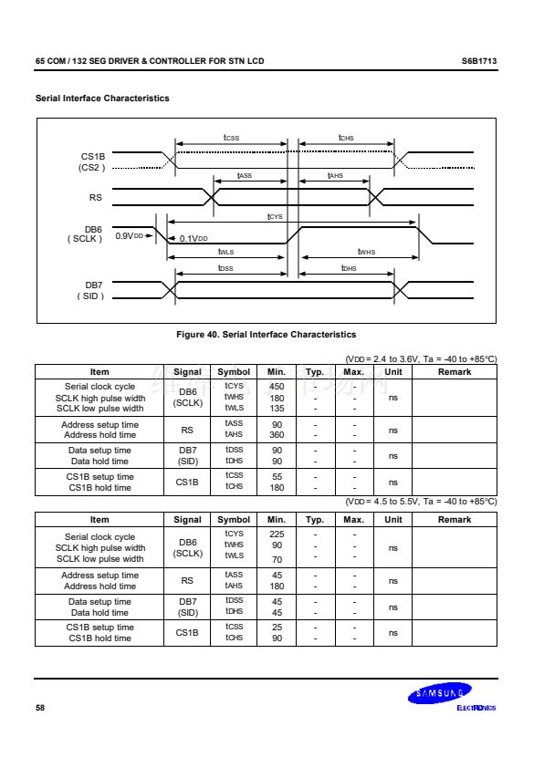
65 COM / 132 SEG DRIVER & CONTROLLER FOR STN LCD
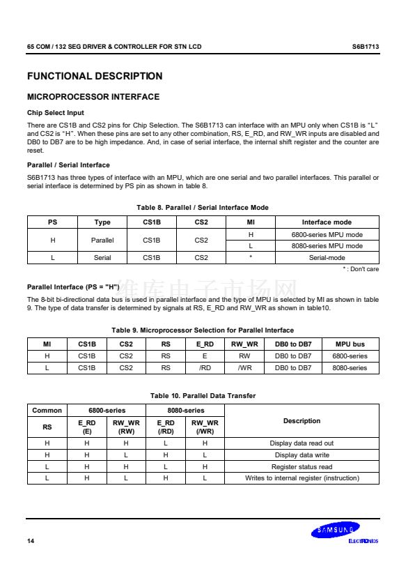
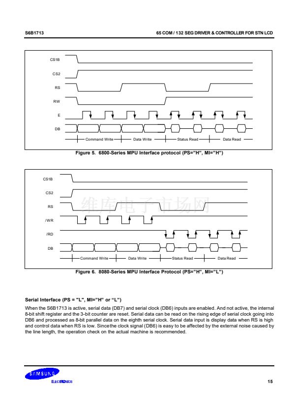
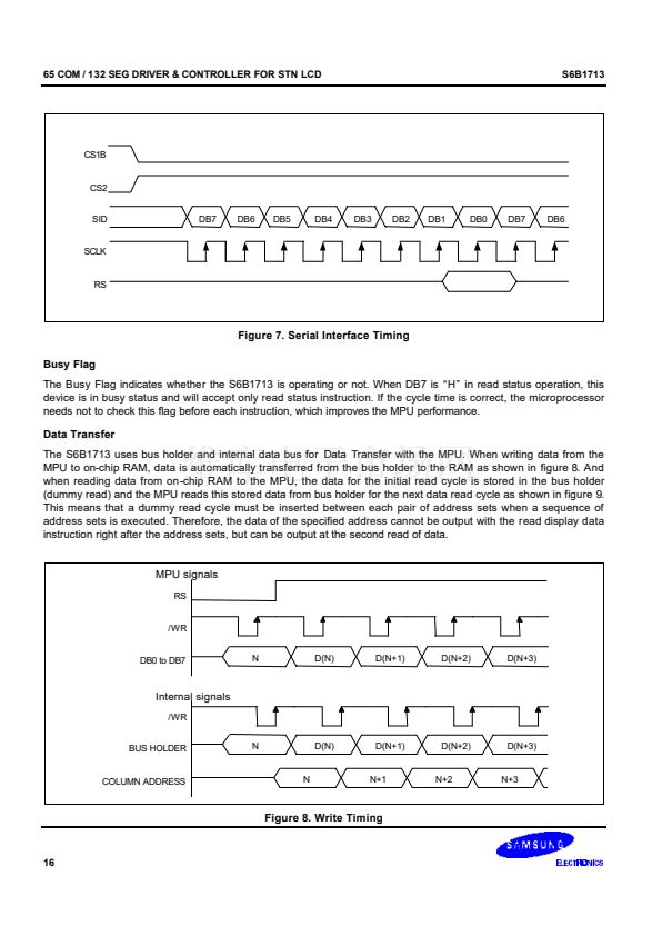
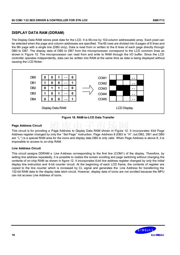
LCD DRIVER OUTPUTS
Table 7. LCD Driver Outputs Pin Description
Name
I/O
Description
LCD segment driver outputs
The display data and the M signal control the output voltage of segment driver.
Display data
SEG1
to
SEG132
H
O
H
L
L
Power save mode
M
H
L
H
L
Segment driver output voltage
Normal display
V0
V
SS
V2
V3
V
SS
Reverse display
V2
V3
V0
V
SS
V
SS
LCD common driver outputs
The internal scanning data and M signal control the output voltage of common driver.
Scan data
COM1
to
COM64
H
O
H
L
L
Power save mode
M
H
L
H
L
Common driver output voltage
V
SS
V0
V1
V4
V
SS
COMS
O
Common output for the icons
The output signals of two pins are same. When not used, these pins should be left open.
In multi-chip (master / slave) mode, all COMS pins on both master and slave units are the
same signal.
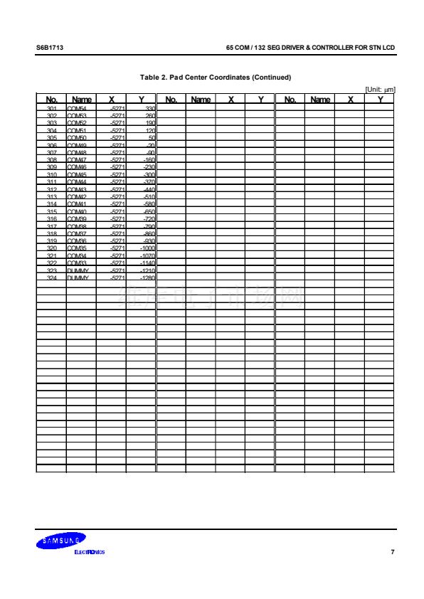
NOTE:
DUMMY - These pins should be opened (floated).
13


 1
1
 2
2
 3
3
 4
4
 5
5
 6
6
 7
7
 8
8
 9
9
 10
10
 11
11
 12
12
 13
13
 14
14
 15
15
 16
16
 17
17
 18
18
 19
19
 20
20
 21
21
 22
22
 23
23
 24
24
 25
25
 26
26
 27
27
 28
28
 29
29
 30
30
 31
31
 32
32
 33
33
 34
34
 35
35
 36
36
 37
37
 38
38
 39
39
 40
40
 41
41
 42
42
 43
43
 44
44
 45
45
 46
46
 47
47
 48
48
 49
49
 50
50
 51
51
 52
52
 53
53
 54
54
 55
55
 56
56
 57
57
 58
58
 59
59
 60
60
 61
61
 62
62
 63
63
 64
64
 65
65
 66
66
 67
67
 68
68
 69
69
 70
70
