Package Description
8.2 Mechanical Dimensions for the MPC7445, 360 CBGA
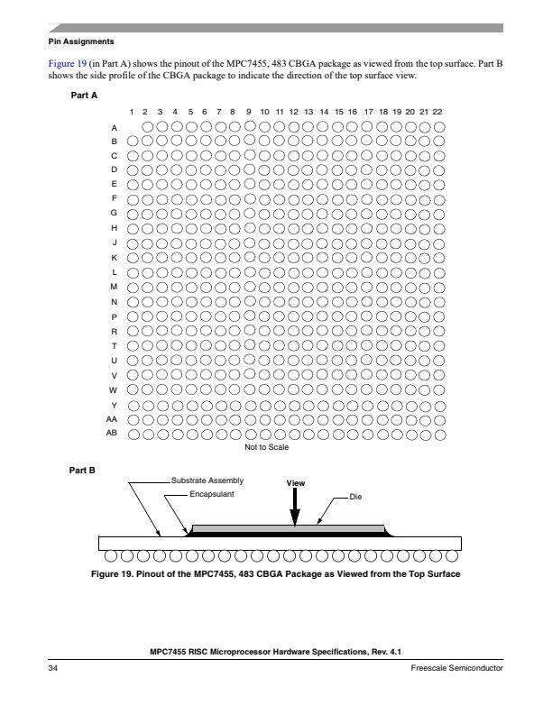
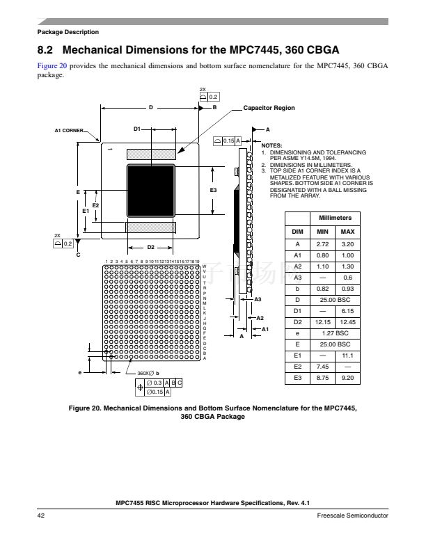
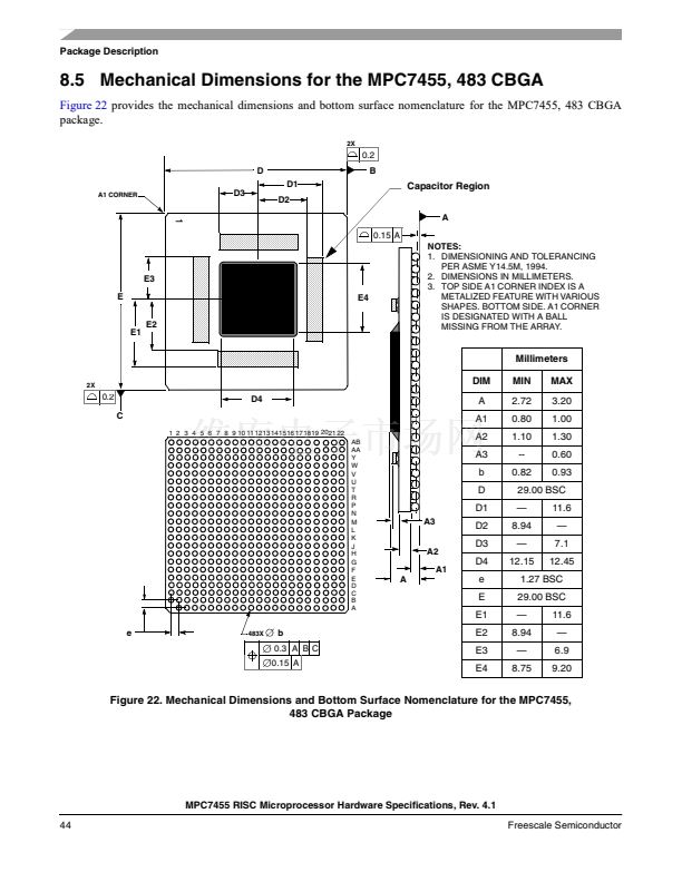
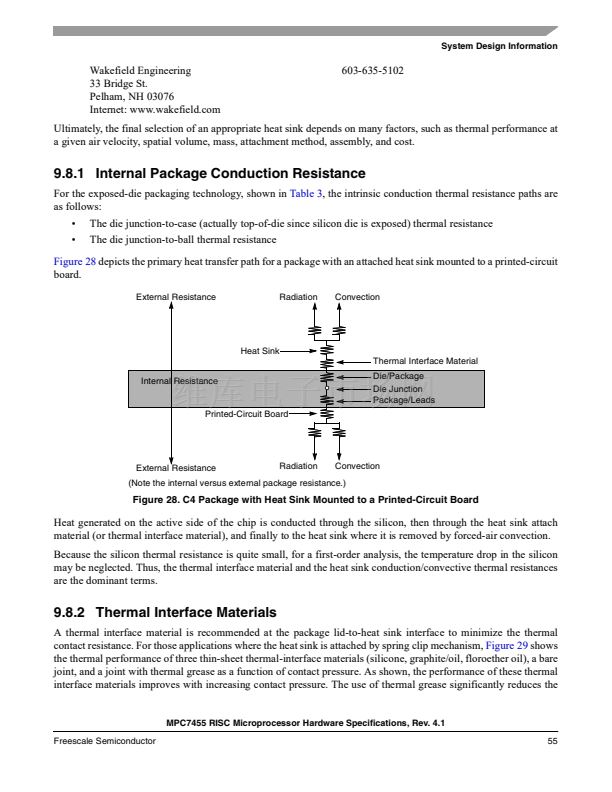
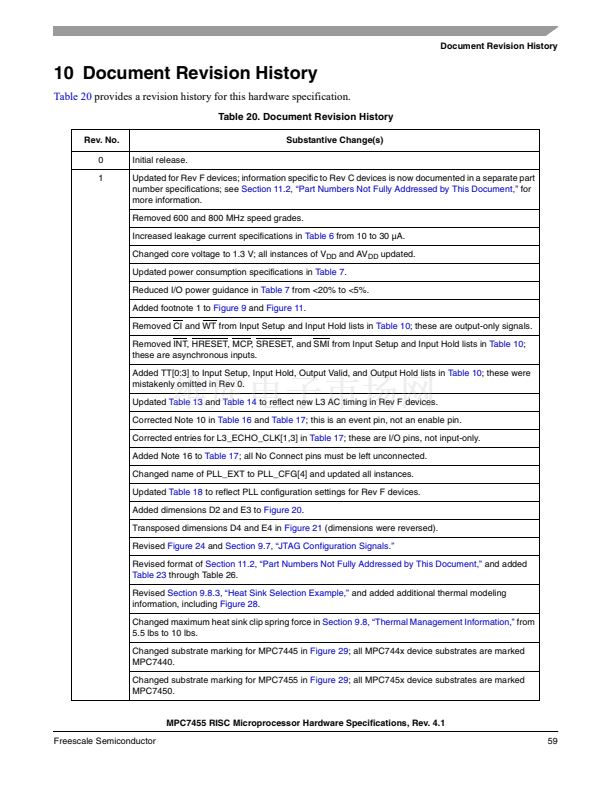
Figure 20
provides the mechanical dimensions and bottom surface nomenclature for the MPC7445, 360 CBGA
package.
2X
0.2
D
B
Capacitor Region
A1 CORNER
D1
0.15 A
A
NOTES:
1. DIMENSIONING AND TOLERANCING
PER ASME Y14.5M, 1994.
2. DIMENSIONS IN MILLIMETERS.
3. TOP SIDE A1 CORNER INDEX IS A
METALIZED FEATURE WITH VARIOUS
SHAPES. BOTTOM SIDE A1 CORNER IS
DESIGNATED WITH A BALL MISSING
FROM THE ARRAY.
1
E3
E2
E1
E
Millimeters
2X
DIM
0.2
C
1 2 3 4 5 6 7 8 9 10 11 1213141516 17 18 19
W
V
U
T
R
P
N
M
L
K
J
H
G
F
E
D
C
B
A
MIN
2.72
0.80
1.10
鈥?/div>
0.82
MAX
3.20
1.00
1.30
0.6
0.93
D2
A
A1
A2
A3
b
A3
A2
A1
A
D
D1
D2
e
E
E1
E2
25.00 BSC
鈥?/div>
12.15
6.15
12.45
1.27 BSC
25.00 BSC
鈥?/div>
7.45
8.75
11.1
鈥?/div>
9.20
e
360X
b
0.3 A B C
0.15 A
E3
Figure 20. Mechanical Dimensions and Bottom Surface Nomenclature for the MPC7445,
360 CBGA Package
MPC7455 RISC Microprocessor Hardware Specifications, Rev. 4.1
42
Freescale Semiconductor


 1
1
 2
2
 3
3
 4
4
 5
5
 6
6
 7
7
 8
8
 9
9
 10
10
 11
11
 12
12
 13
13
 14
14
 15
15
 16
16
 17
17
 18
18
 19
19
 20
20
 21
21
 22
22
 23
23
 24
24
 25
25
 26
26
 27
27
 28
28
 29
29
 30
30
 31
31
 32
32
 33
33
 34
34
 35
35
 36
36
 37
37
 38
38
 39
39
 40
40
 41
41
 42
42
 43
43
 44
44
 45
45
 46
46
 47
47
 48
48
 49
49
 50
50
 51
51
 52
52
 53
53
 54
54
 55
55
 56
56
 57
57
 58
58
 59
59
 60
60
 61
61
 62
62
 63
63
 64
64
