鈥?Interrupt Status Register 0 (ISTAT0)
鈥?Interrupt Status Register 1 (ISTAT1)
鈥?Interrupt Debug Register (IDBG)
The following CPU core registers are also used in processing
interrupts:
鈥?Interrupt Stack Pointer (ISP)
鈥?Interrupt Base Register (INTBASE)
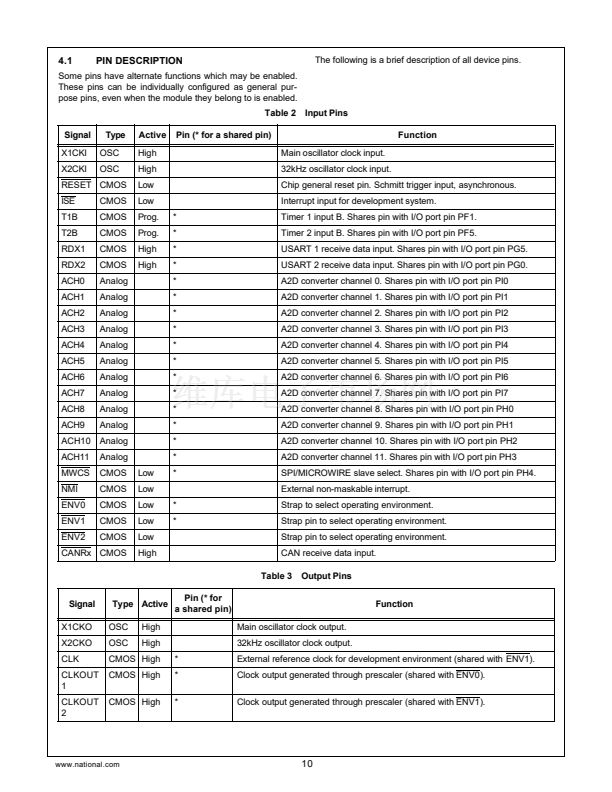
10.4.1
Non-Maskable Interrupt Status Register
(NMISTAT)
10.4.3
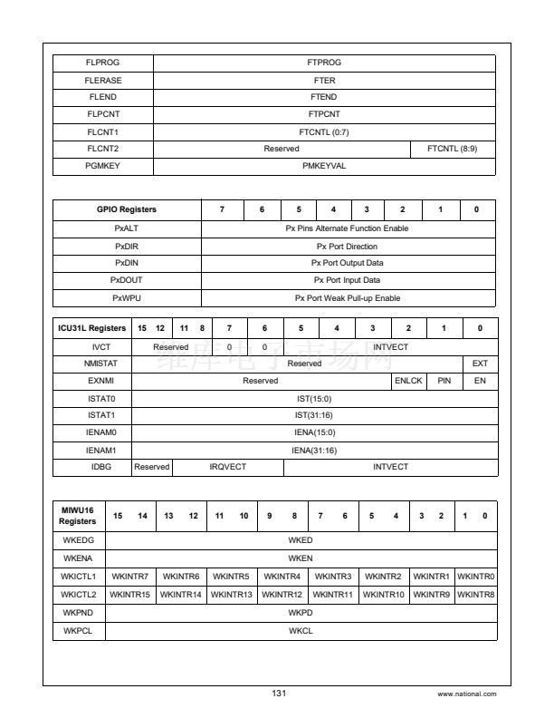
Interrupt Vector Register (IVCT)
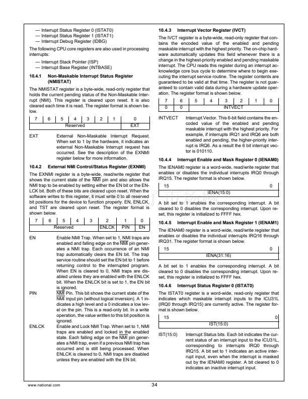
The NMISTAT register is a byte-wide, read-only register that
holds the current pending status of the Non-Maskable Inter-
rupt (NMI). This register is cleared upon reset. It is also
cleared each time it is read. The register format is shown be-
low.
7
6
5
4
3
Reserved
2
1
0
EXT
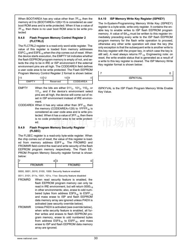
The IVCT register is a byte-wide, read-only register that con-
tains the encoded value of the enabled and pending
maskable interrupt with the highest priority. The on-chip hard-
ware automatically updates this field whenever there is a
change in the highest-priority enabled and pending maskable
interrupt. The CPU reads this register during an interrupt ac-
knowledge core bus cycle to determine where to begin exe-
cuting the interrupt service routine. The register contents are
guaranteed to be valid at that time. The register is not guar-
anteed to contain valid data during a hardware update oper-
ation. The register format is shown below.
7
0
INTVECT
6
0
5
4
3
2
INTVECT
1
0
EXT
External Non-Maskable Interrupt Request.
When set to 1 by the hardware, it indicates an
external Non-Maskable Interrupt request has
occurred. See the description of the EXNMI
register below for more information.
External NMI Control/Status Register (EXNMI)
Interrupt Vector. This 6-bit field contains the en-
coded value of the enabled and pending
maskable interrupt with the highest priority. For
example, if interrupts IRQ1 and IRQ6 are both
enabled and pending, the higher-priority inter-
rupt is IRQ6. As a result the 6 bit interrupt vec-
tor is 010110.
10.4.4
Interrupt Enable and Mask Register 0 (IENAM0)
10.4.2
The EXNMI register is a byte-wide, read/write register that
shows the current state of the NMI pin and also allows the
NMI trap to be enabled by setting either the EN bit or the EN-
LCK bit. Both of these bits are cleared upon reset. When the
software writes to this register, it must write 0 to all reserved
bit positions for the device to function properly. EN, ENLCK,
and TST are cleared upon reset. The register format is
shown below.
7
6
5
4
Reserved
3
2
ENLCK
1
PIN
0
EN
The IENAM0 register is a word-wide, read/write register that
enables or disables the individual interrupts IRQ0 through
IRQ15. The register format is shown below.
15
IENA(15:0)
A bit set to 1 enables the corresponding interrupt. A bit
cleared to 0 disables the corresponding interrupt. Upon re-
set, this register is initialized to FFFF hex.
10.4.5
Interrupt Enable and Mask Register 1 (IENAM1)
0
EN
PIN
ENLCK
Enable NMI Trap. When set to 1, NMI traps are
enabled and falling edge on the NMI pin gener-
ates a NMI trap. Each occurrence of an NMI
trap automatically clears the EN bit. The trap
service routine should set the EN bit to 1 before
returning control to the interrupted program.
When EN is cleared to 0, NMI traps are dis-
abled unless they are enabled with the ENLCK
bit. When the ENLCK bit is set to 1, the EN bit
is ignored.
NMI Pin. This bit shows the current state of the
NMI input pin (without logical inversion). A 1 in-
dicates a high level and a 0 indicates a low lev-
el on the pin. This is a read-only bit. In a write
operation, the value written to this bit position is
ignored.
Enable and Lock NMI Trap. When set to 1, NMI
traps are enabled and locked in the enabled
state. Each falling edge on the NMI pin gener-
ates a NMI trap, even if a previous NMI trap has
occurred and is still being processed. When
ENLCK is cleared to 0, NMI traps are disabled
unless they are enabled with the EN bit.
The IENAM0 register is a word-wide, read/write register that
enables or disables the individual interrupts IRQ16 through
IRQ31. The register format is shown below.
15
IENA(31:16)
A bit set to 1 enables the corresponding interrupt. A bit
cleared to 0 disables the corresponding interrupt. Upon re-
set, this register is initialized to FFFF hex.
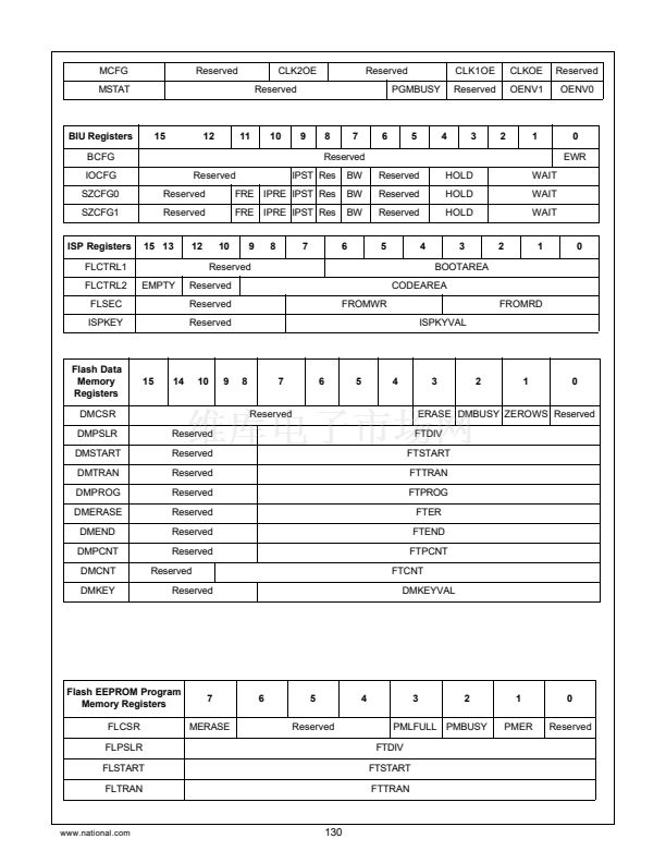
10.4.6
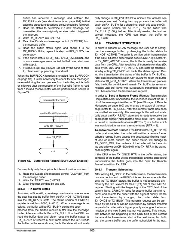
Interrupt Status Register 0 (ISTAT0)
0
The ISTAT0 register is a word-wide, read-only register that
indicates which maskable interrupt inputs to the ICU31L
(IRQ0 through IRQ15) are currently active. The register for-
mat is shown below.
15
IST(15:0)
IST(15:0)
Interrupt Status bits. Each bit indicates the cur-
rent status of an interrupt input to the ICU31L,
corresponding to interrupts IRQ0 through
IRQ15. A bit set to 1 indicates an active inter-
rupt input, even when the interrupt is masked
out by the IENAM0 register. A bit cleared to 0
indicates an inactive interrupt input.
0
www.national.com
34


 1
1
 2
2
 3
3
 4
4
 5
5
 6
6
 7
7
 8
8
 9
9
 10
10
 11
11
 12
12
 13
13
 14
14
 15
15
 16
16
 17
17
 18
18
 19
19
 20
20
 21
21
 22
22
 23
23
 24
24
 25
25
 26
26
 27
27
 28
28
 29
29
 30
30
 31
31
 32
32
 33
33
 34
34
 35
35
 36
36
 37
37
 38
38
 39
39
 40
40
 41
41
 42
42
 43
43
 44
44
 45
45
 46
46
 47
47
 48
48
 49
49
 50
50
 51
51
 52
52
 53
53
 54
54
 55
55
 56
56
 57
57
 58
58
 59
59
 60
60
 61
61
 62
62
 63
63
 64
64
 65
65
 66
66
 67
67
 68
68
 69
69
 70
70
 71
71
 72
72
 73
73
 74
74
 75
75
 76
76
 77
77
 78
78
 79
79
 80
80
 81
81
 82
82
 83
83
 84
84
 85
85
 86
86
 87
87
 88
88
 89
89
 90
90
 91
91
 92
92
 93
93
 94
94
 95
95
 96
96
 97
97
 98
98
 99
99
 100
100
 101
101
 102
102
 103
103
 104
104
 105
105
 106
106
 107
107
 108
108
 109
109
 110
110
 111
111
 112
112
 113
113
 114
114
 115
115
 116
116
 117
117
 118
118
 119
119
 120
120
 121
121
 122
122
 123
123
 124
124
 125
125
 126
126
 127
127
 128
128
 129
129
 130
130
 131
131
 132
132
 133
133
 134
134
 135
135
 136
136
 137
137
 138
138
 139
139
 140
140
 141
141
 142
142
 143
143
 144
144
 145
145
 146
146
 147
147
 148
148
 149
149
 150
150
 151
151
 152
152
 153
153
 154
154
 155
155
 156
156
