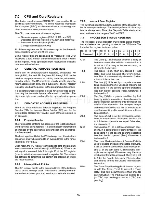
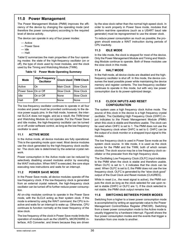
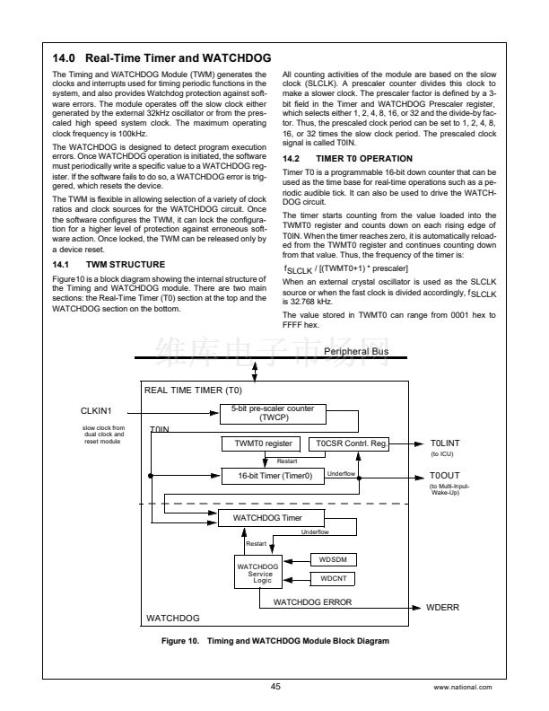
Peripheral Bus
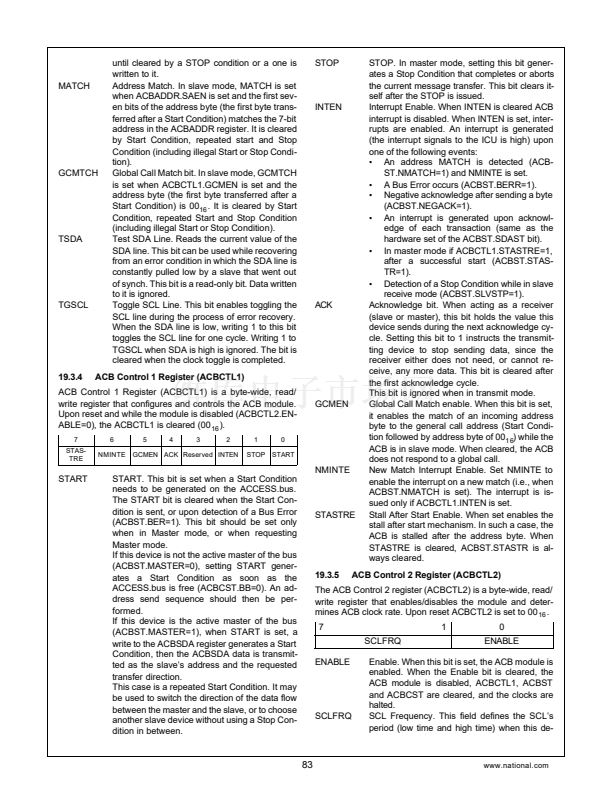
15
..........
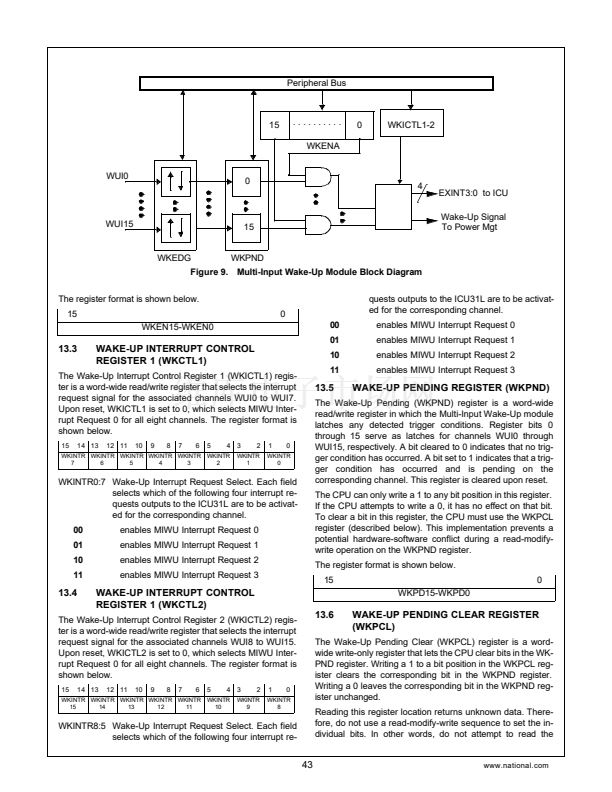
WKENA
0
WKICTL1-2
WUI0
0
4
EXINT3:0 to ICU
Wake-Up Signal
To Power Mgt
WUI15
15
WKEDG
WKPND
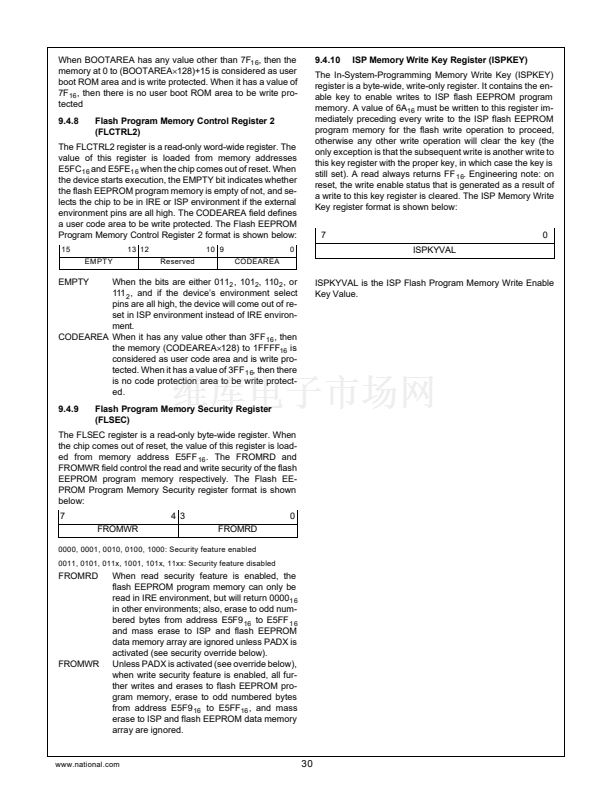
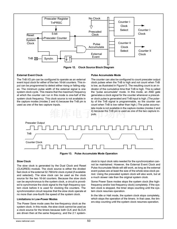
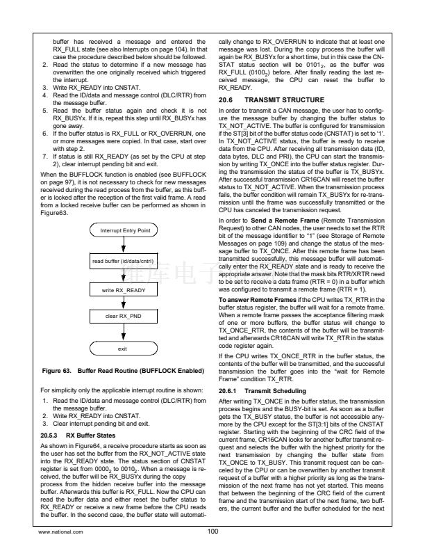
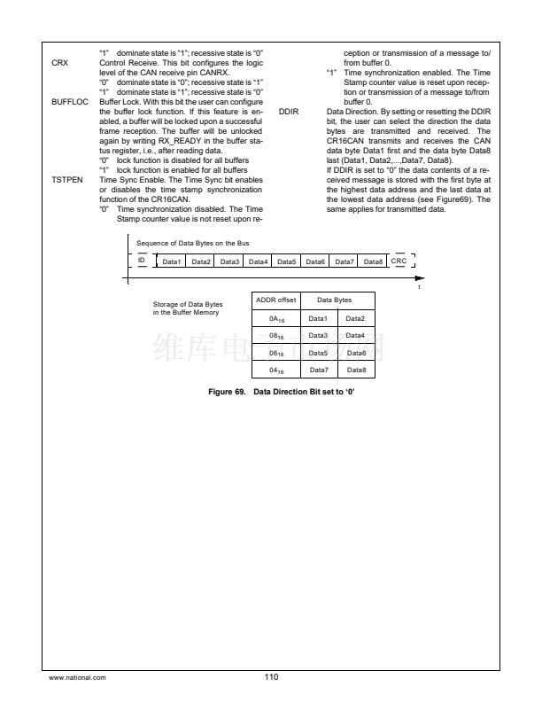
Figure 9. Multi-Input Wake-Up Module Block Diagram
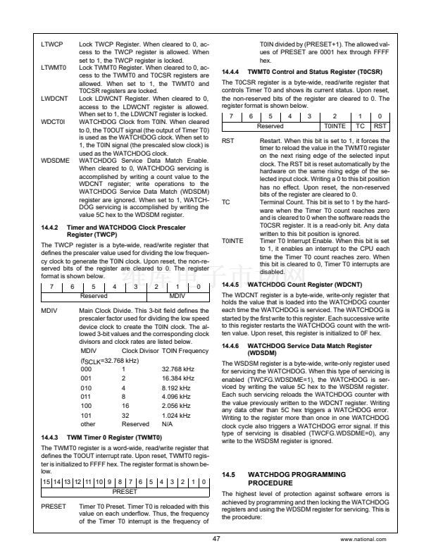
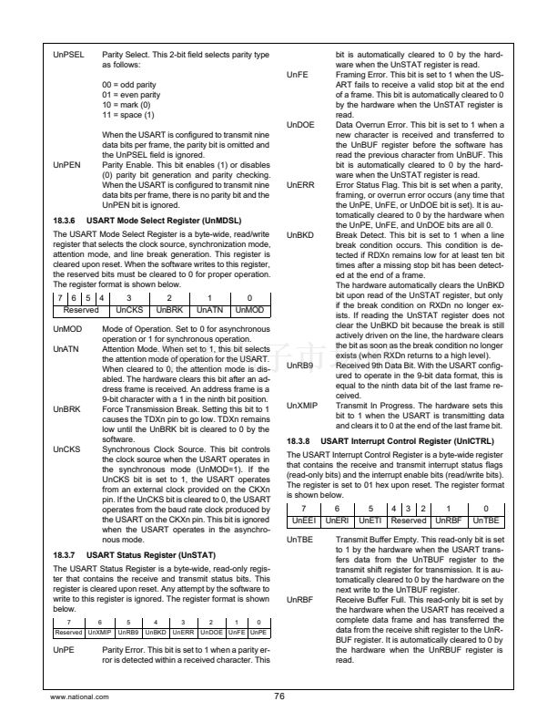
The register format is shown below.
15
WKEN15-WKEN0
0
00
01
10
11
quests outputs to the ICU31L are to be activat-
ed for the corresponding channel.
enables MIWU Interrupt Request 0
enables MIWU Interrupt Request 1
enables MIWU Interrupt Request 2
enables MIWU Interrupt Request 3
13.3
WAKE-UP INTERRUPT CONTROL
REGISTER 1 (WKCTL1)
The Wake-Up Interrupt Control Register 1 (WKICTL1) regis-
ter is a word-wide read/write register that selects the interrupt
request signal for the associated channels WUI0 to WUI7.
Upon reset, WKICTL1 is set to 0, which selects MIWU Inter-
rupt Request 0 for all eight channels. The register format is
shown below.
15
14 13
12 11
10
9
8
7
6
5
4 3
2
1
0
WKINTR WKINTR WKINTR WKINTR WKINTR WKINTR
7
6
5
4
3
2
WKINTR
1
WKINTR
0
13.5
WAKE-UP PENDING REGISTER (WKPND)
WKINTR0:7 Wake-Up Interrupt Request Select. Each field
selects which of the following four interrupt re-
quests outputs to the ICU31L are to be activat-
ed for the corresponding channel.
00
01
10
11
enables MIWU Interrupt Request 0
enables MIWU Interrupt Request 1
enables MIWU Interrupt Request 2
enables MIWU Interrupt Request 3
The Wake-Up Pending (WKPND) register is a word-wide
read/write register in which the Multi-Input Wake-Up module
latches any detected trigger conditions. Register bits 0
through 15 serve as latches for channels WUI0 through
WUI15, respectively. A bit cleared to 0 indicates that no trig-
ger condition has occurred. A bit set to 1 indicates that a trig-
ger condition has occurred and is pending on the
corresponding channel. This register is cleared upon reset.
The CPU can only write a 1 to any bit position in this register.
If the CPU attempts to write a 0, it has no effect on that bit.
To clear a bit in this register, the CPU must use the WKPCL
register (described below). This implementation prevents a
potential hardware-software conflict during a read-modify-
write operation on the WKPND register.
The register format is shown below.
15
WKPD15-WKPD0
0
13.4
WAKE-UP INTERRUPT CONTROL
REGISTER 1 (WKCTL2)
13.6
The Wake-Up Interrupt Control Register 2 (WKICTL2) regis-
ter is a word-wide read/write register that selects the interrupt
request signal for the associated channels WUI8 to WUI15.
Upon reset, WKICTL2 is set to 0, which selects MIWU Inter-
rupt Request 0 for all eight channels. The register format is
shown below.
15
14 13
12 11
10
9
8
7
6
5
4 3
2
1
0
WKINTR WKINTR WKINTR WKINTR WKINTR WKINTR
15
14
13
12
11
10
WKINTR
9
WKINTR
8
WAKE-UP PENDING CLEAR REGISTER
(WKPCL)
The Wake-Up Pending Clear (WKPCL) register is a word-
wide write-only register that lets the CPU clear bits in the WK-
PND register. Writing a 1 to a bit position in the WKPCL reg-
ister clears the corresponding bit in the WKPND register.
Writing a 0 leaves the corresponding bit in the WKPND reg-
ister unchanged.
Reading this register location returns unknown data. There-
fore, do not use a read-modify-write sequence to set the in-
dividual bits. In other words, do not attempt to read the
WKINTR8:5 Wake-Up Interrupt Request Select. Each field
selects which of the following four interrupt re-
43
www.national.com


 1
1
 2
2
 3
3
 4
4
 5
5
 6
6
 7
7
 8
8
 9
9
 10
10
 11
11
 12
12
 13
13
 14
14
 15
15
 16
16
 17
17
 18
18
 19
19
 20
20
 21
21
 22
22
 23
23
 24
24
 25
25
 26
26
 27
27
 28
28
 29
29
 30
30
 31
31
 32
32
 33
33
 34
34
 35
35
 36
36
 37
37
 38
38
 39
39
 40
40
 41
41
 42
42
 43
43
 44
44
 45
45
 46
46
 47
47
 48
48
 49
49
 50
50
 51
51
 52
52
 53
53
 54
54
 55
55
 56
56
 57
57
 58
58
 59
59
 60
60
 61
61
 62
62
 63
63
 64
64
 65
65
 66
66
 67
67
 68
68
 69
69
 70
70
 71
71
 72
72
 73
73
 74
74
 75
75
 76
76
 77
77
 78
78
 79
79
 80
80
 81
81
 82
82
 83
83
 84
84
 85
85
 86
86
 87
87
 88
88
 89
89
 90
90
 91
91
 92
92
 93
93
 94
94
 95
95
 96
96
 97
97
 98
98
 99
99
 100
100
 101
101
 102
102
 103
103
 104
104
 105
105
 106
106
 107
107
 108
108
 109
109
 110
110
 111
111
 112
112
 113
113
 114
114
 115
115
 116
116
 117
117
 118
118
 119
119
 120
120
 121
121
 122
122
 123
123
 124
124
 125
125
 126
126
 127
127
 128
128
 129
129
 130
130
 131
131
 132
132
 133
133
 134
134
 135
135
 136
136
 137
137
 138
138
 139
139
 140
140
 141
141
 142
142
 143
143
 144
144
 145
145
 146
146
 147
147
 148
148
 149
149
 150
150
 151
151
 152
152
 153
153
 154
154
 155
155
 156
156
