鈥?/div>
A flexible interrupt scheme with
鈥?four separate system level interrupt requests
鈥?a total of 16 interrupt sources each with a separate in-
terrupt pending flag and interrupt enable bit
16.1
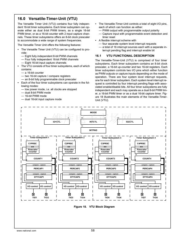
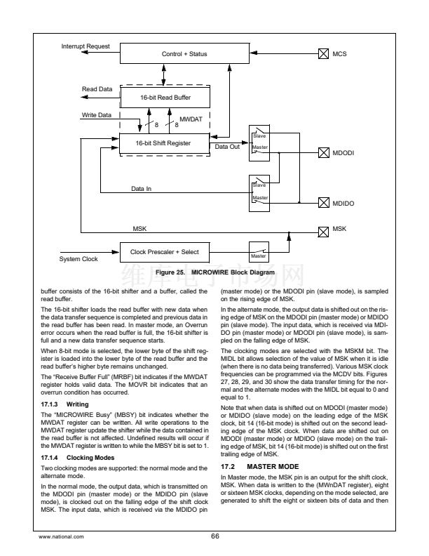
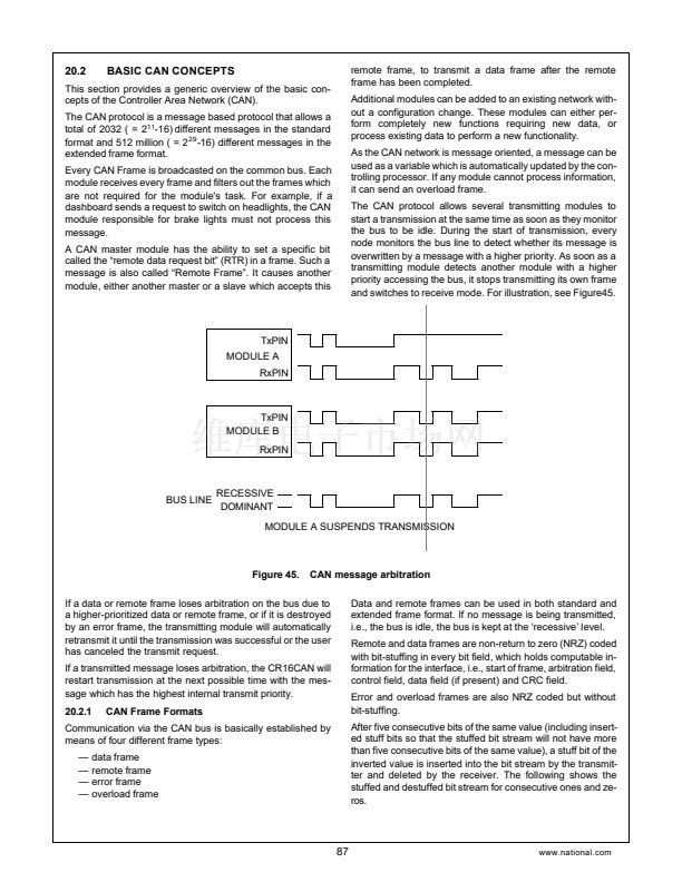
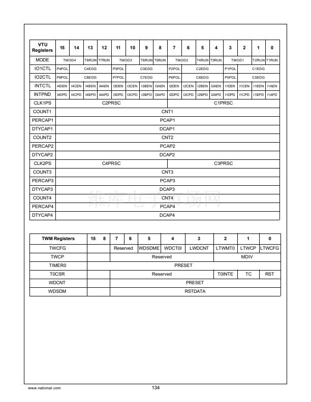
VTU FUNCTIONAL DESCRIPTION
The Versatile-Timer-Unit (VTU) is comprised of four timer
subsystems. Each timer subsystem contains an 8-bit clock
prescaler, a 16-bit up-counter and two 16-bit registers. Each
timer subsystem controls two I/O pins which either function
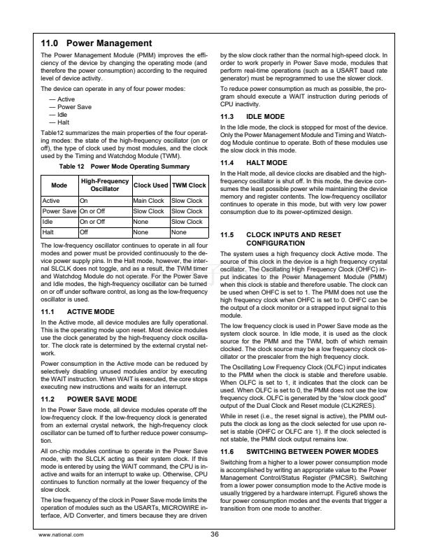
as PWM outputs or capture inputs depending on the mode of
operation. There are four system level interrupt requests,
one for each timer subsystem. Each system level interrupt re-
quest is controlled by four interrupt pending flags with asso-
ciated enable/disable bits. All four timer subsystems are fully
independent and each may operate as a dual 8-bit PWM tim-
er, a 16-bit PWM timer or as a dual 16-bit capture timer. Fig-
ure 18 illustrates the main elements of the Versatile-Timer-
Unit (VTU).
0
15
MODE
15
0
15
0
15
0
IO1CTL
15
INTCTL
0
IO2CTL
INTPND
Timer Subsystem 1
7
0
7
Timer Subsystem 2
0
7
Timer Subsystem 3
0
7
Timer Subsystem 4
0
C1PRSC
==
Prescaler
Counter
15
0
15
C2PRSC
==
Prescaler
Counter
0
15
C3PRSC
==
Prescaler
Counter
0
15
C4PRSC
==
Prescaler
Counter
0
COUNT1
compare - capture
COUNT2
compare - capture
COUNT3
compare - capture
COUNT4
compare - capture
PERCAP1
compare - capture
PERCAP2
compare - capture
PERCAP3
compare - capture
PERCAP4
compare - capture
DTYCAP1
DTYCAP2
DTYCAP3
DTYCAP4
I/O control
I/O control
I/O control
I/O control
I/O control
I/O control
I/O control
I/O control
TIO1
TIO2
TIO3
TIO4
TIO5
TIO6
TIO7
TIO8
Figure 18. VTU Block Diagram
www.national.com
58


 1
1
 2
2
 3
3
 4
4
 5
5
 6
6
 7
7
 8
8
 9
9
 10
10
 11
11
 12
12
 13
13
 14
14
 15
15
 16
16
 17
17
 18
18
 19
19
 20
20
 21
21
 22
22
 23
23
 24
24
 25
25
 26
26
 27
27
 28
28
 29
29
 30
30
 31
31
 32
32
 33
33
 34
34
 35
35
 36
36
 37
37
 38
38
 39
39
 40
40
 41
41
 42
42
 43
43
 44
44
 45
45
 46
46
 47
47
 48
48
 49
49
 50
50
 51
51
 52
52
 53
53
 54
54
 55
55
 56
56
 57
57
 58
58
 59
59
 60
60
 61
61
 62
62
 63
63
 64
64
 65
65
 66
66
 67
67
 68
68
 69
69
 70
70
 71
71
 72
72
 73
73
 74
74
 75
75
 76
76
 77
77
 78
78
 79
79
 80
80
 81
81
 82
82
 83
83
 84
84
 85
85
 86
86
 87
87
 88
88
 89
89
 90
90
 91
91
 92
92
 93
93
 94
94
 95
95
 96
96
 97
97
 98
98
 99
99
 100
100
 101
101
 102
102
 103
103
 104
104
 105
105
 106
106
 107
107
 108
108
 109
109
 110
110
 111
111
 112
112
 113
113
 114
114
 115
115
 116
116
 117
117
 118
118
 119
119
 120
120
 121
121
 122
122
 123
123
 124
124
 125
125
 126
126
 127
127
 128
128
 129
129
 130
130
 131
131
 132
132
 133
133
 134
134
 135
135
 136
136
 137
137
 138
138
 139
139
 140
140
 141
141
 142
142
 143
143
 144
144
 145
145
 146
146
 147
147
 148
148
 149
149
 150
150
 151
151
 152
152
 153
153
 154
154
 155
155
 156
156
