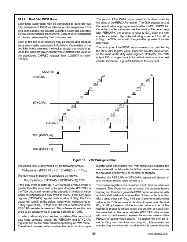
refers to timer subsystem 1 but equally applies to the other
three timer subsystems.
7
0
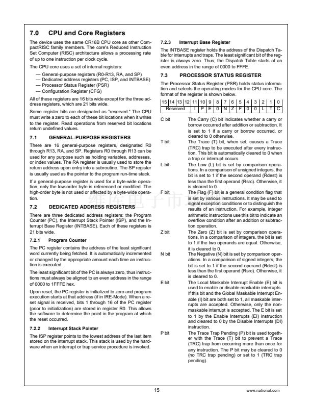
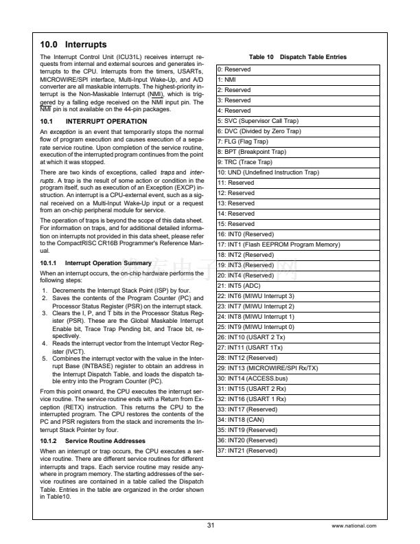
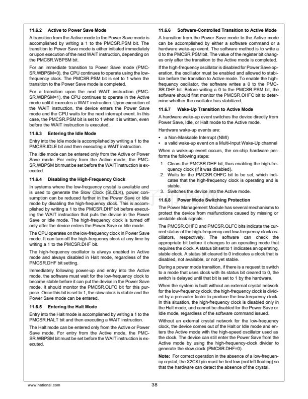
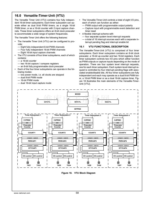
ed with them. All interrupt pending flags are denoted IxAPD
through IxDPD where 鈥渪鈥?relates to the specific timer sub-
system. There is one system level interrupt request for each
of the four timer subsystems.
Figure23 illustrates the interrupt structure of the versatile
timer module.
C1PRSC
==
Prescaler
Counter
T1RUN
15
TMOD1=11
I1AEN
0
[15:0]
I1BEN
I1CEN
I1DEN
System
Interrupt
Request 1
Restart
COUNT1[15:0]
capture
PERCAP1[15:0]
capture
I1APD
I1BPD
I1CPD
DTYCAP1[15:0]
cap
rst
2
0
cap
rst
I1DPD
2
0
C1EDG
TIO1
C2EDG
TIO2
I4AEN
I4BEN
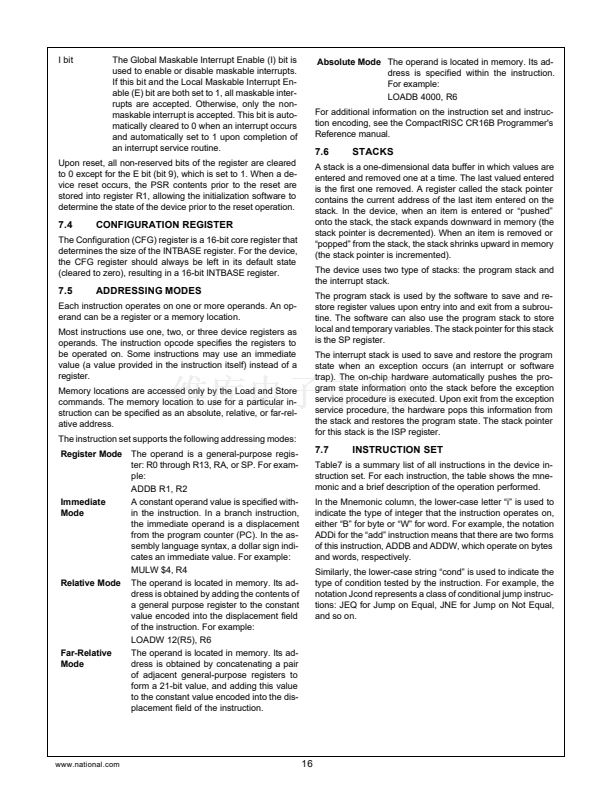
Figure 22. VTU Dual 16-bit Capture Mode
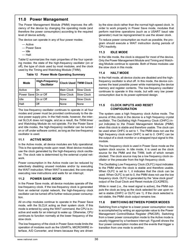
16.1.4
Low Power Mode
I4APD
I4BPD
I4CPD
I4DPD
I4CEN
I4DEN
System
Interrupt
Request 4
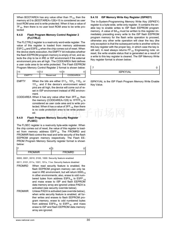
In case a timer subsystem is not used, the user can place it
in a low-power-mode. All clocks to a timer subsystem are
stopped and the counter and prescaler contents are frozen
once low-power-mode is entered. The user may continue to
write to the MODE, INTCTL, IOxCTL and CLKxPS registers.
Write operations to the INTPND register are allowed; but if a
timer subsystem is in low power mode, its associated inter-
rupt pending bits cannot be cleared. The user cannot write to
the COUNTx, PERCAPx and DTYCAPx registers of a timer
subsystem while it is in low-power-mode. All registers can be
read at any time.
16.1.5
Interrupts
Figure 23. VTU Interrupt Request Structure
Each of the timer pending flags - IxAPD through IxDPD - is
set by a specific hardware event depending on the mode of
operation, i.e., PWM or Capture mode. Table17 outlines the
specific hardware events relative to the operation mode
which cause an interrupt pending flag to be set.
The Versatile-Timer-Unit (VTU) has a total of 16 interrupt
sources, four for each of the four timer subsystems. All inter-
rupt sources have a pending flag and an enable bit associat-
Table 17
Pending Flag
IxAPD
IxBPD
IxCPD
IxDPD
16.1.6
Dual 8-bit PWM Mode
Low Byte Duty Cycle match
Low Byte Period match
High Byte Duty Cycle match
High Byte Period match
ISE Mode operation
VTU Interrupt Sources
16-bit PWM Mode
Duty Cycle match
Period match
N/A
N/A
Capture Mode
Capture to DTYCAPx
Capture to PERCAPx
Counter Overflow
N/A
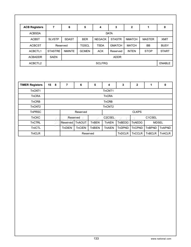
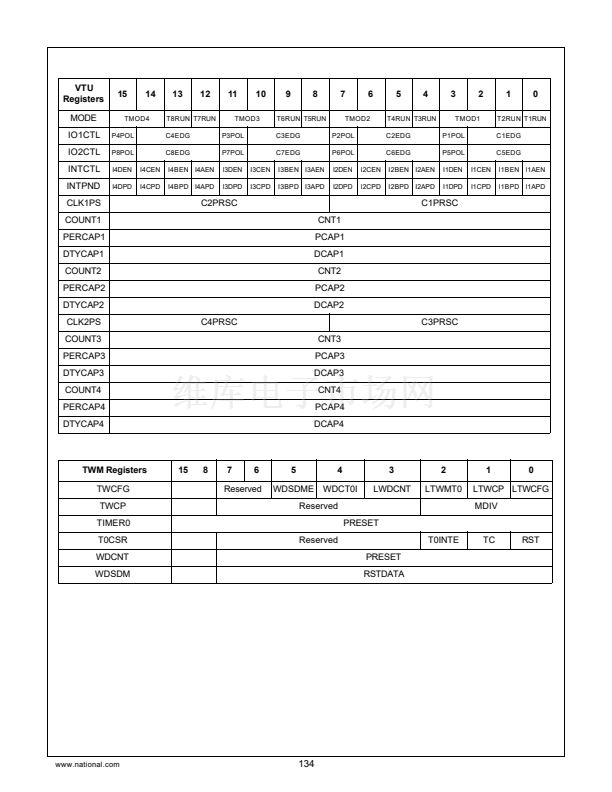
16.2
VTU REGISTERS
The VTU supports breakpoint operation of the In-System-
Emulator (ISE). If FREEZE is asserted, all timer counter
clocks will be inhibited and the current value of the timer reg-
isters will be frozen; in capture mode, all further capture
events are disabled. Once FREEZE becomes inactive,
counting will resume from the previous value and the capture
input events are re-enabled.
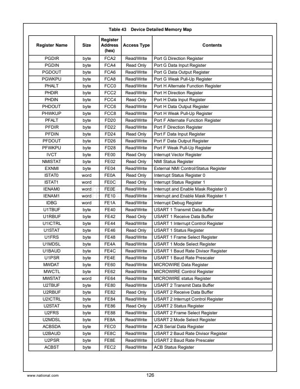
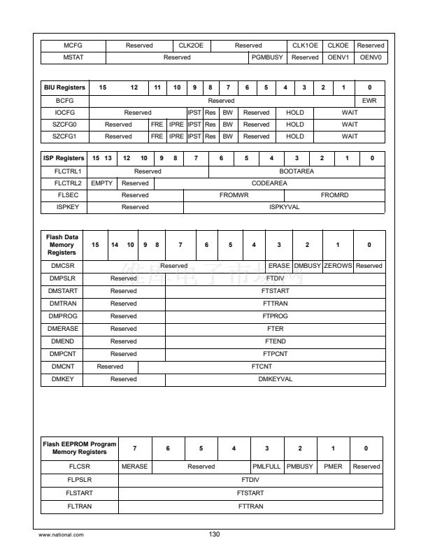
The Versatile-Timer-Unit contains a total of 19 user accessi-
ble registers. All registers are word-wide and are initialized to
a known value upon reset. All software accesses to the VTU
registers must be word accesses.
61
www.national.com


 1
1
 2
2
 3
3
 4
4
 5
5
 6
6
 7
7
 8
8
 9
9
 10
10
 11
11
 12
12
 13
13
 14
14
 15
15
 16
16
 17
17
 18
18
 19
19
 20
20
 21
21
 22
22
 23
23
 24
24
 25
25
 26
26
 27
27
 28
28
 29
29
 30
30
 31
31
 32
32
 33
33
 34
34
 35
35
 36
36
 37
37
 38
38
 39
39
 40
40
 41
41
 42
42
 43
43
 44
44
 45
45
 46
46
 47
47
 48
48
 49
49
 50
50
 51
51
 52
52
 53
53
 54
54
 55
55
 56
56
 57
57
 58
58
 59
59
 60
60
 61
61
 62
62
 63
63
 64
64
 65
65
 66
66
 67
67
 68
68
 69
69
 70
70
 71
71
 72
72
 73
73
 74
74
 75
75
 76
76
 77
77
 78
78
 79
79
 80
80
 81
81
 82
82
 83
83
 84
84
 85
85
 86
86
 87
87
 88
88
 89
89
 90
90
 91
91
 92
92
 93
93
 94
94
 95
95
 96
96
 97
97
 98
98
 99
99
 100
100
 101
101
 102
102
 103
103
 104
104
 105
105
 106
106
 107
107
 108
108
 109
109
 110
110
 111
111
 112
112
 113
113
 114
114
 115
115
 116
116
 117
117
 118
118
 119
119
 120
120
 121
121
 122
122
 123
123
 124
124
 125
125
 126
126
 127
127
 128
128
 129
129
 130
130
 131
131
 132
132
 133
133
 134
134
 135
135
 136
136
 137
137
 138
138
 139
139
 140
140
 141
141
 142
142
 143
143
 144
144
 145
145
 146
146
 147
147
 148
148
 149
149
 150
150
 151
151
 152
152
 153
153
 154
154
 155
155
 156
156
