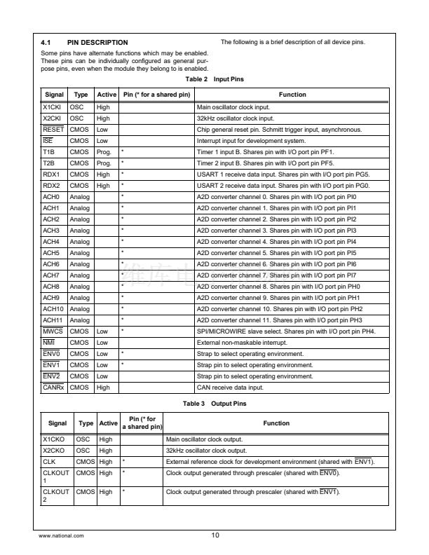
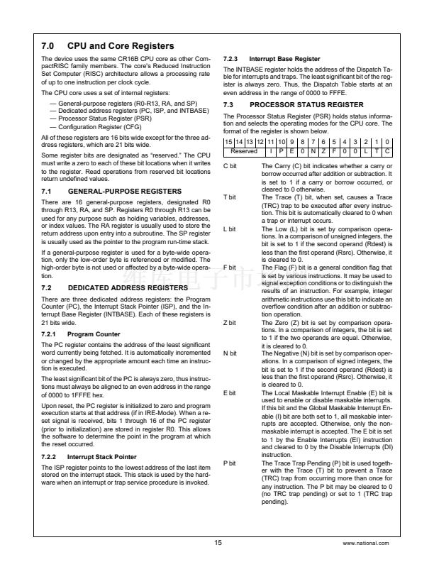
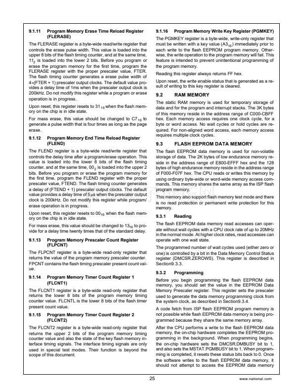
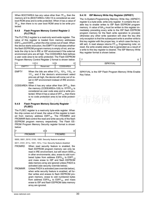
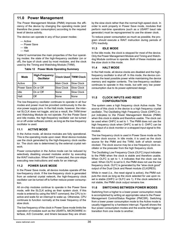
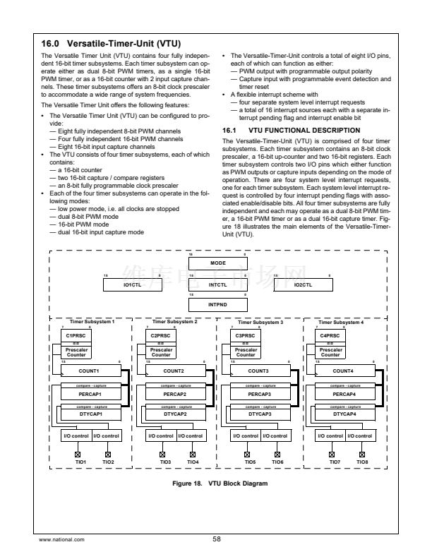
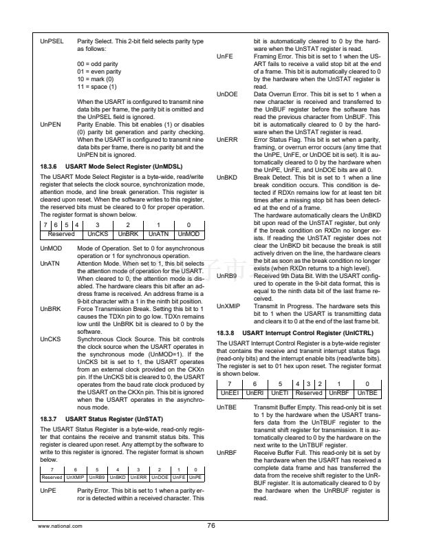
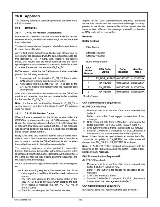
16.2.1
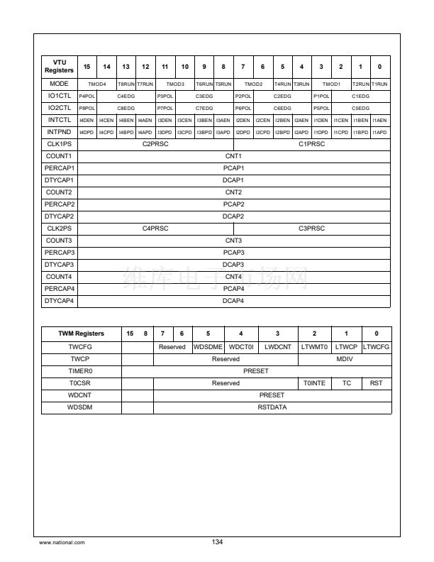
Mode Control Register (MODE)
The Mode Control (MODE) registries a word-wide read/write
register which controls the mode selection of all four timer
subsystems. The register is cleared (0000
1 6
) upon reset.
15
14
13
T8RUN
5
T4RUN
12
T7RUN
4
T3RUN
11
10
9
T6RUN
1
T2RUN
8
T5RUN
0
T1RUN
TMOD4
7
6
TMOD3
3
2
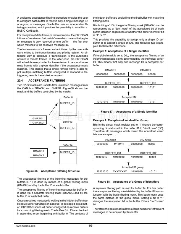
value of this three bit field has no effect while
operating in PWM mode.
CxEDG
000
001
010
011
100
101
110
111
PxPOL
Capture
rising edge
falling edge
rising edge
falling edge
both edges
both edges
both edges
both edges
Counter Reset
No
No
Yes
Yes
No
rising edge
falling edge
both edges
TMOD2
TMOD1
TxRUN
TMODx
Timer start/stop. If set (1), the associated
counter and clock prescaler is started depend-
ing on the mode of operation. Once set, the
clock to the clock prescaler and the counter are
enabled and the counter will increment each
time the clock prescaler counter value matches
the value defined in the associated clock pres-
caler field (CxPRSC).
Timer System Operating Mode. This 2-bit wide
field enables or disables the Timer Subsystem
and defines it鈥檚 operating mode.
00:
Low-Power-Mode enabled. All clocks to
the counter subsystem are stopped. The
counter is stopped regardless of the val-
ue of the TxRUN bits. Read operations
to the Timer Subsystem will return the
last value; the user shall not perform any
write operations to the Timer Subsystem
while it is disabled since those will be ig-
nored.
Dual 8-bit PWM mode enabled. Each 8-
bit counter may individually be started or
stopped via its associated TxRUN bit.
The TIOx pins will function as PWM out-
puts.
16-bit PWM mode enabled. The two 8-
bit counters are concatenated to form a
single 16-bit counter. The counter may
be started or stopped with the lower of
the two TxRUN bits, i.e. T1RUN,
T3RUN, T5RUN and T7RUN. The TIOx
pins will function as PWM outputs.
Capture Mode enabled. Both 8-bit
counters are concatenated and operate
as a single 16-bit counter. The counter
may be started or stopped with the lower
of the two TxRUN bits, i.e., T1RUN,
T3RUN, T5RUN and T7RUN. The TIOx
pins will function as capture inputs.
PWM Polarity. While operating in PWM mode
the bit defines the output polarity of the corre-
sponding PWM output (TIOx).
0=
The PWM output is set (1) upon the 00
16
to 01
1 6
transition of the counter and will
be reset (0) once the counter value
matches the duty cycle value.
The PWM output is reset (0) upon the
00
1 6
to 01
16
transition of the counter and
will be set (1) once the counter value
matches the duty cycle value.
1=
01:
Once a counter is stopped, the output will assume the value
of PxPOL, i.e., its initial value. The PxPOL bit has no effect
while operating in capture mode.
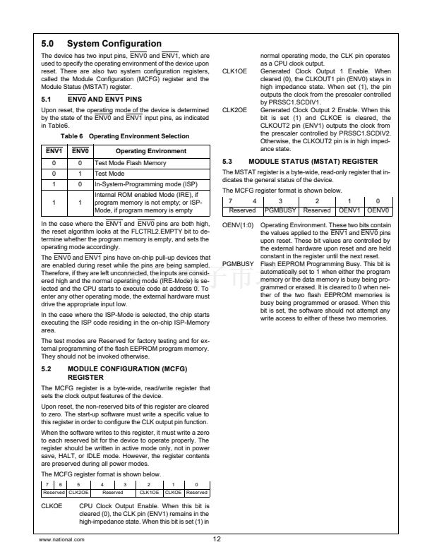
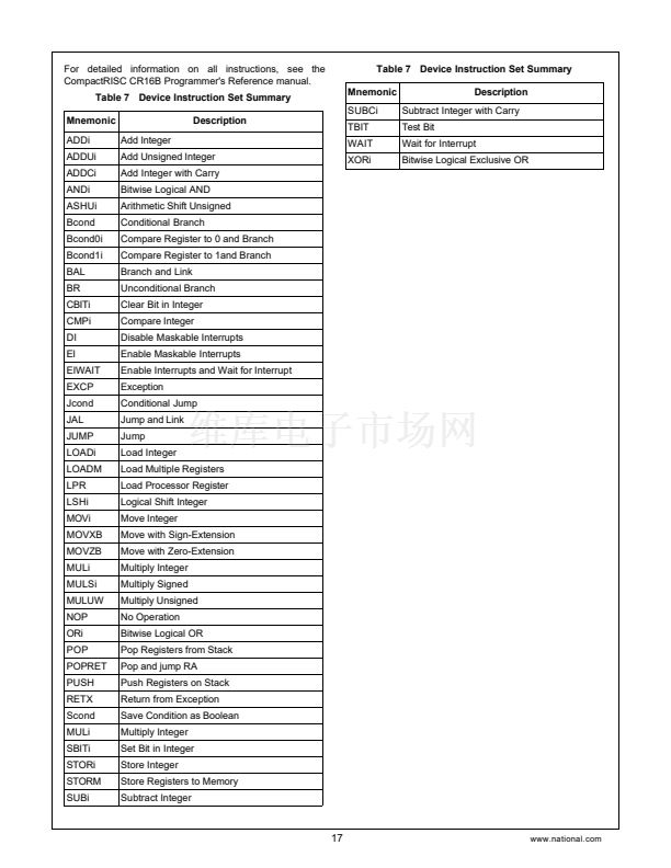
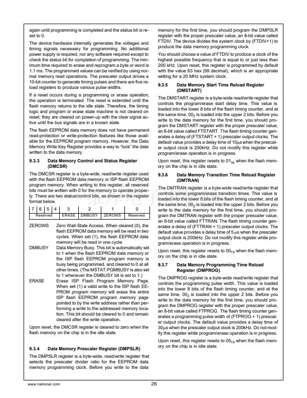
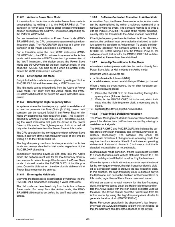
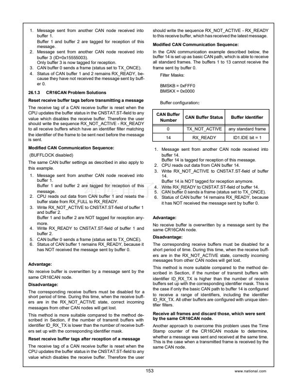
16.2.3
I/O Control Register 2 (IO2CTL)
10:
The I/O Control Register 2 (IO2CTL) is a word-wide read/
write register. The register controls the functionality of the
I/O pins TIO5 through TIO8 depending on the selected mode
of operation. The register is cleared (0000) upon reset.
15
14
12
11
10
8
7
6
4
3
2
0
P8POL C8EDG P7POL C7EDG P6POL C6EDG P5POL C5EDG
The functionality of the bit fields of the IO2CTL register is
identical to the ones described in the IO1CTL register sec-
tion.
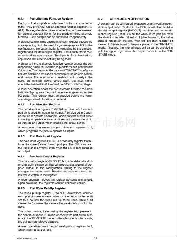
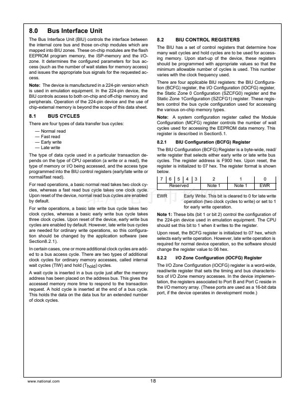
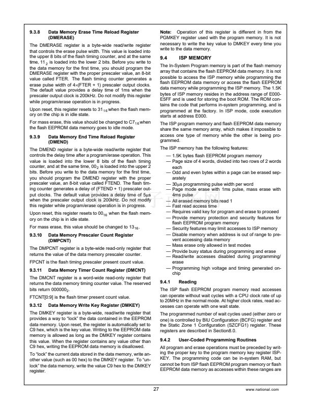
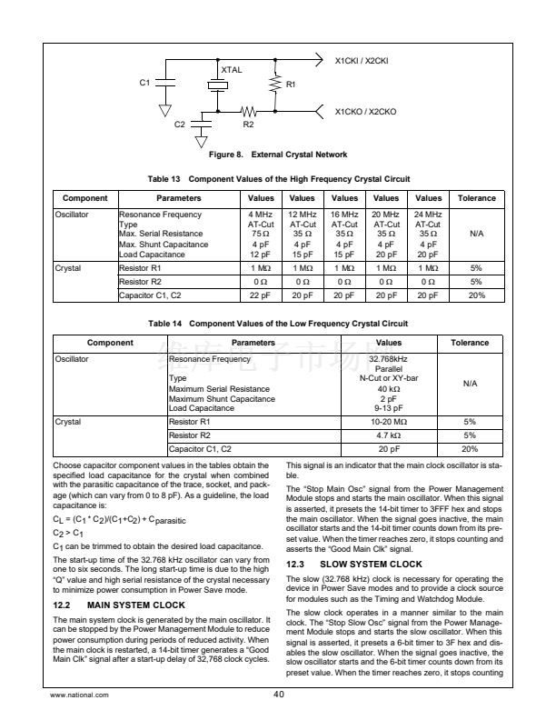
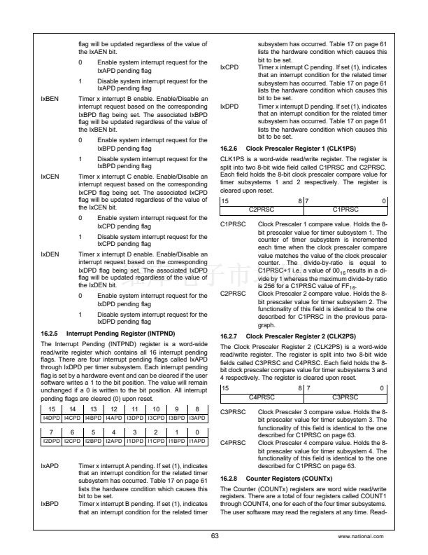
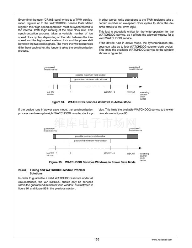
16.2.4
Interrupt Control Register (INTCTL)
11:
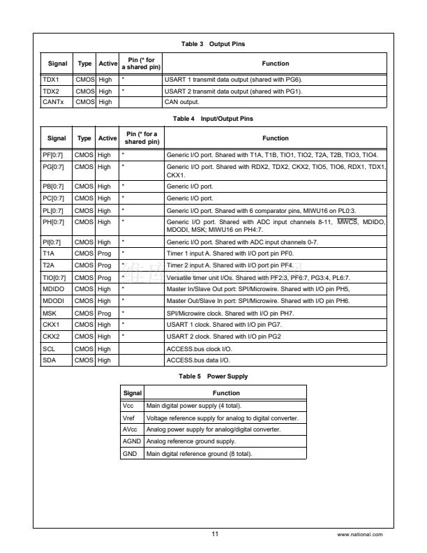
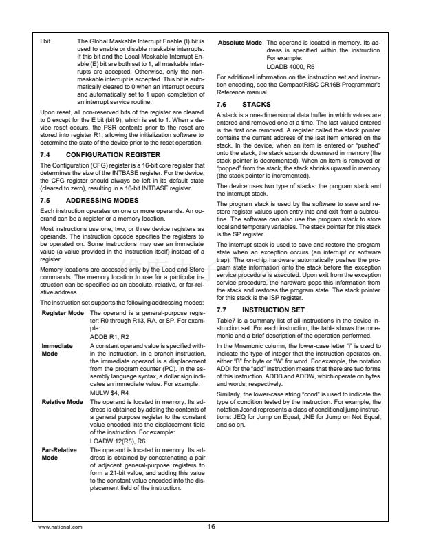
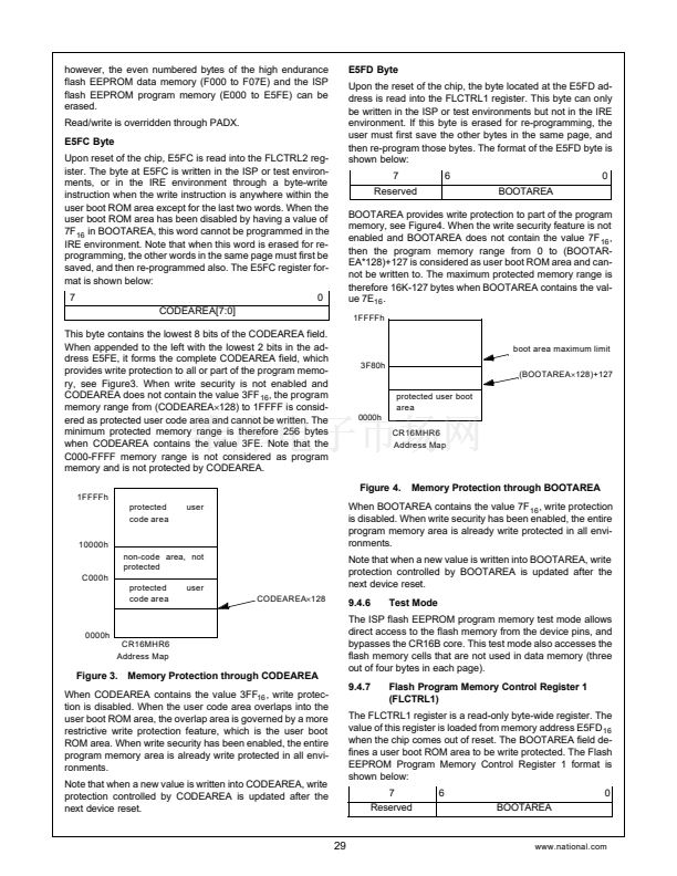
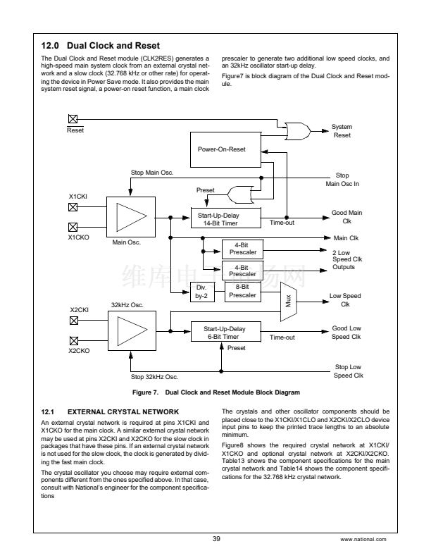
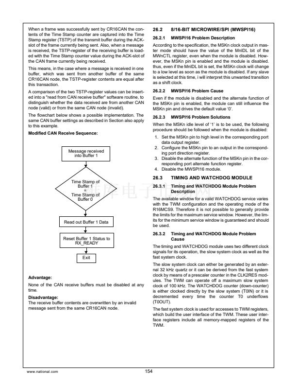
16.2.2
I/O Control Register 1 (IO1CTL)
The Interrupt Control (INTCTL) register is a word-wide read/
write register. It contains the interrupt enable bits for all 16 in-
terrupt sources of the Versatile-Timer-Unit. Each interrupt en-
able bit corresponds to an interrupt pending flag located in
the Interrupt Pending Register (INTPND). All INTCTL regis-
ter bits are solely under software control. The register is
cleared (0000
1 6
) upon reset..
15
14
13
12
11
10
9
8
I4DEN I4CEN I4BEN I4AEN I3DEN I3CEN I3BEN I3AEN
The I/O Control Register 1 (IO1CTL) is a word-wide read/
write register. The register controls the functionality of the
I/O pins TIO1 through TIO4 depending on the selected mode
of operation. The register is cleared (0000
1 6
) upon reset.
15
P4POL
14
12
11
10
8
7
6
4
3
2
0
C4EDG P3POL
C3EDG P2POL
C2EDG P1POL
C1EDG
7
6
5
4
3
2
1
0
I2DEN I2CEN I2BEN I2AEN I1DEN I1CEN I1BEN I1AEN
IxAEN
CxEDG
Capture Edge Control. Defines the polarity of a
capture event and the reset of the counter. The
Timer x interrupt A enable. Enable/Disable an
interrupt request based on the corresponding
IxAPD flag being set. The associated IxAPD
www.national.com
62


 1
1
 2
2
 3
3
 4
4
 5
5
 6
6
 7
7
 8
8
 9
9
 10
10
 11
11
 12
12
 13
13
 14
14
 15
15
 16
16
 17
17
 18
18
 19
19
 20
20
 21
21
 22
22
 23
23
 24
24
 25
25
 26
26
 27
27
 28
28
 29
29
 30
30
 31
31
 32
32
 33
33
 34
34
 35
35
 36
36
 37
37
 38
38
 39
39
 40
40
 41
41
 42
42
 43
43
 44
44
 45
45
 46
46
 47
47
 48
48
 49
49
 50
50
 51
51
 52
52
 53
53
 54
54
 55
55
 56
56
 57
57
 58
58
 59
59
 60
60
 61
61
 62
62
 63
63
 64
64
 65
65
 66
66
 67
67
 68
68
 69
69
 70
70
 71
71
 72
72
 73
73
 74
74
 75
75
 76
76
 77
77
 78
78
 79
79
 80
80
 81
81
 82
82
 83
83
 84
84
 85
85
 86
86
 87
87
 88
88
 89
89
 90
90
 91
91
 92
92
 93
93
 94
94
 95
95
 96
96
 97
97
 98
98
 99
99
 100
100
 101
101
 102
102
 103
103
 104
104
 105
105
 106
106
 107
107
 108
108
 109
109
 110
110
 111
111
 112
112
 113
113
 114
114
 115
115
 116
116
 117
117
 118
118
 119
119
 120
120
 121
121
 122
122
 123
123
 124
124
 125
125
 126
126
 127
127
 128
128
 129
129
 130
130
 131
131
 132
132
 133
133
 134
134
 135
135
 136
136
 137
137
 138
138
 139
139
 140
140
 141
141
 142
142
 143
143
 144
144
 145
145
 146
146
 147
147
 148
148
 149
149
 150
150
 151
151
 152
152
 153
153
 154
154
 155
155
 156
156
