Interrupt Request
Control + Status
MCS
Read Data
16-bit Read Buffer
Write Data
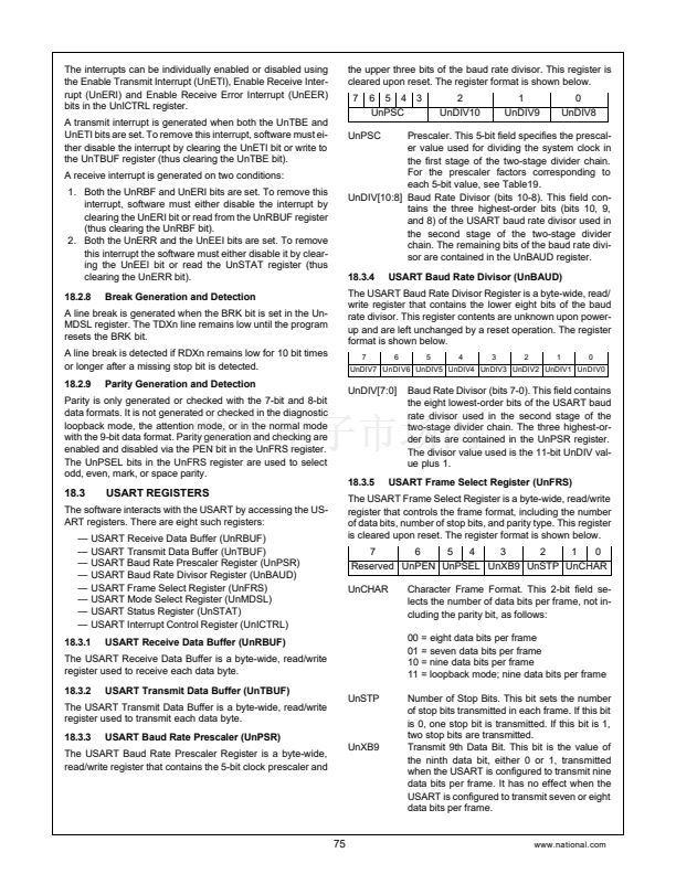
8
8
MWDAT
Slave
16-bit Shift Register
Data Out
Master
MDODI
Data In
Slave
Master
MDIDO
MSK
MSK
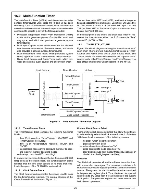
Clock Prescaler + Select
System Clock
Master
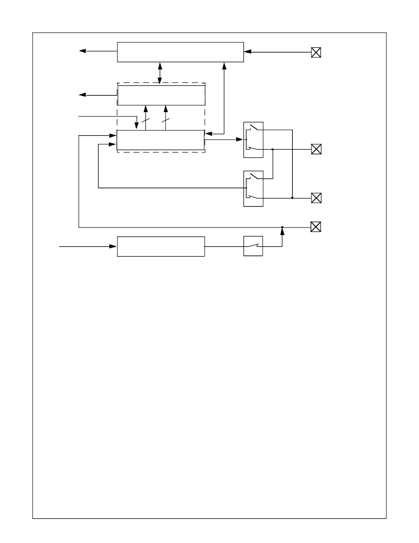
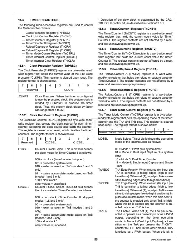
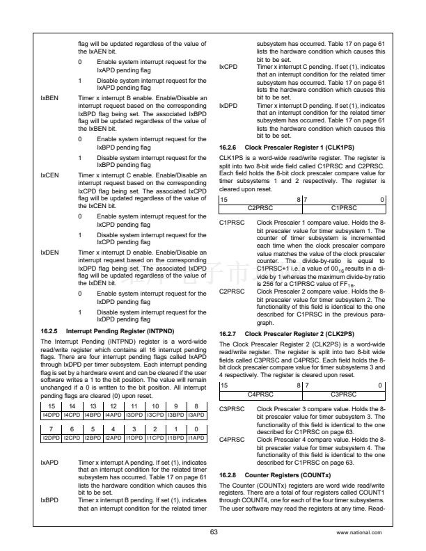
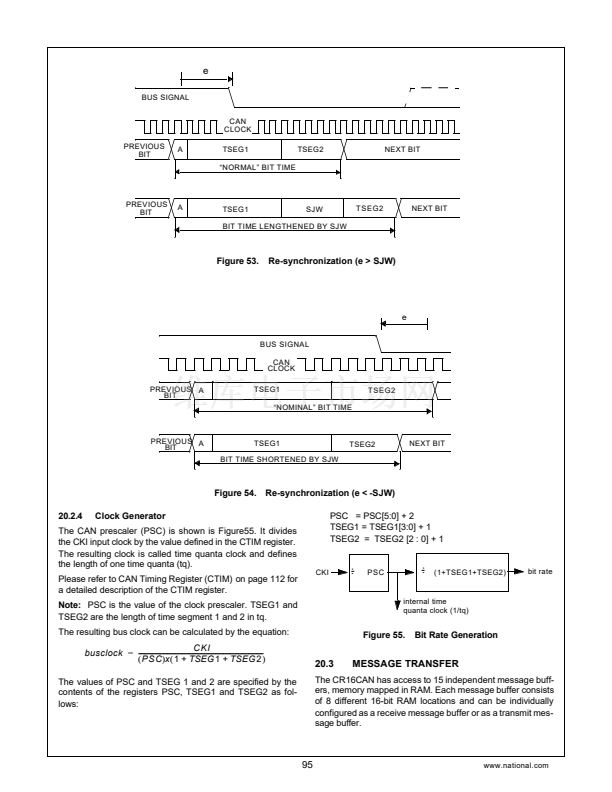
Figure 25. MICROWIRE Block Diagram
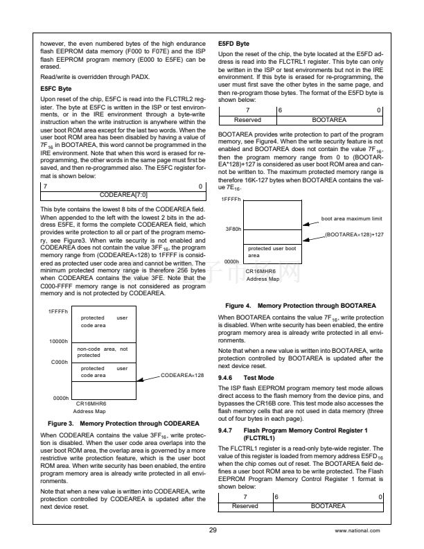
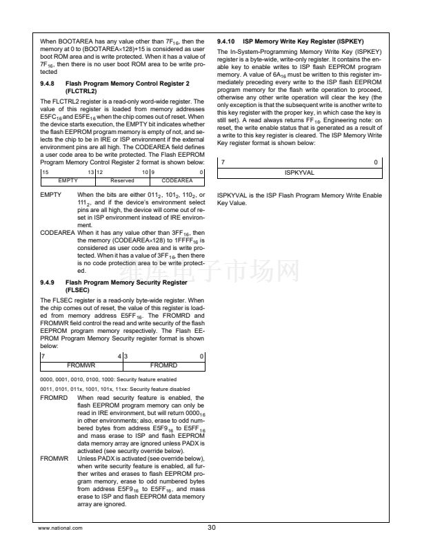
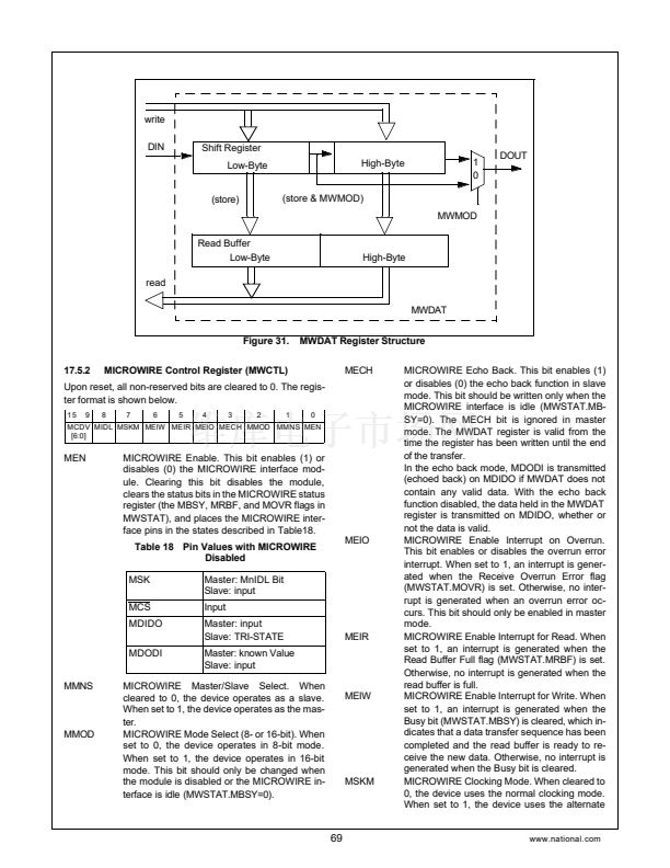
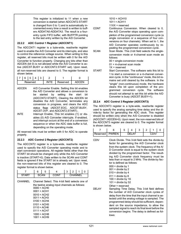
buffer consists of the 16-bit shifter and a buffer, called the
read buffer.
The 16-bit shifter loads the read buffer with new data when
the data transfer sequence is completed and previous data in
the read buffer has been read. In master mode, an Overrun
error occurs when the read buffer is full, the 16-bit shifter is
full and a new data transfer sequence starts.
When 8-bit mode is selected, the lower byte of the shift reg-
ister is loaded into the lower byte of the read buffer and the
read buffer鈥檚 higher byte remains unchanged.
The 鈥淩eceive Buffer Full鈥?(MRBF) bit indicates if the MWDAT
register holds valid data. The MOVR bit indicates that an
overrun condition has occurred.
17.1.3
Writing
(master mode) or the MDODI pin (slave mode), is sampled
on the rising edge of MSK.
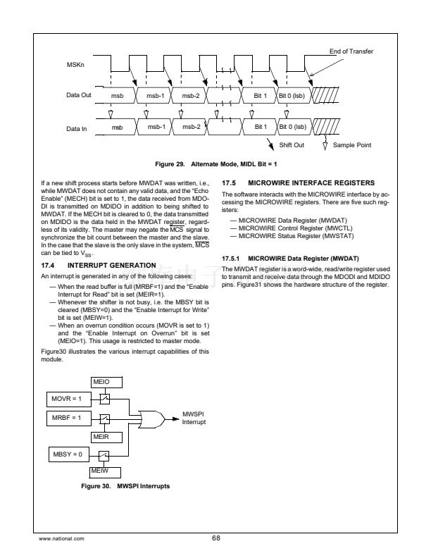
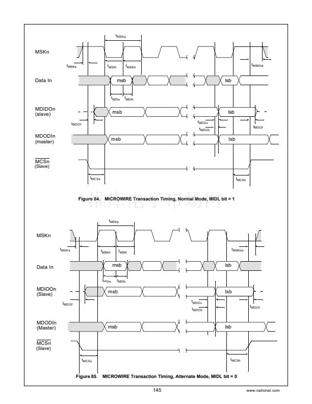
In the alternate mode, the output data is shifted out on the ris-
ing edge of MSK on the MDODI pin (master mode) or MDIDO
pin (slave mode). The input data, which is received via MDI-
DO pin (master mode) or MDODI pin (slave mode), is sam-
pled on the falling edge of MSK.
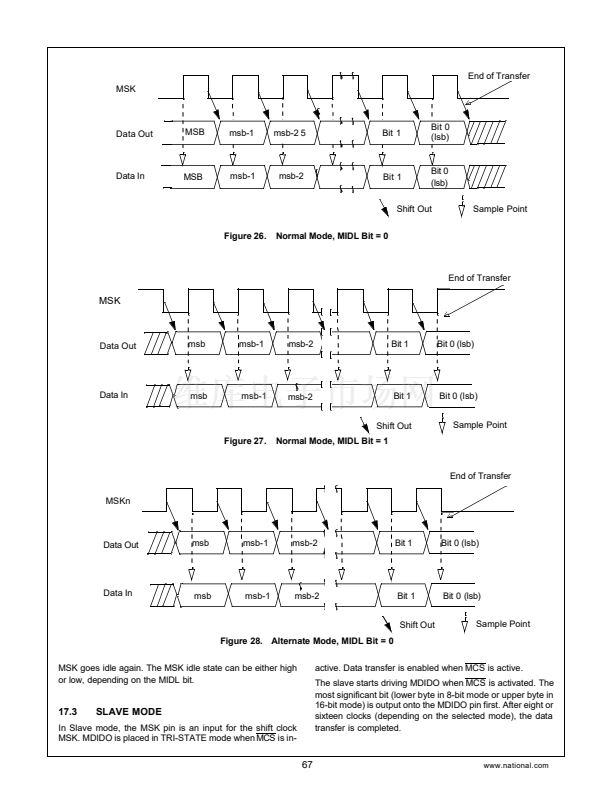
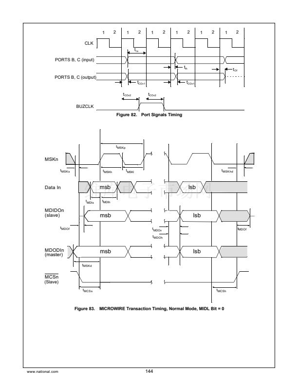
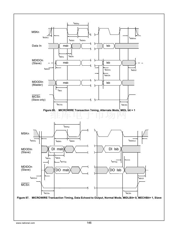
The clocking modes are selected with the MSKM bit. The
MIDL bit allows selection of the value of MSK when it is idle
(when there is no data being transferred). Various MSK clock
frequencies can be programmed via the MCDV bits. Figures
27, 28, 29, and 30 show the data transfer timing for the nor-
mal and the alternate modes with the MIDL bit equal to 0 and
equal to 1.
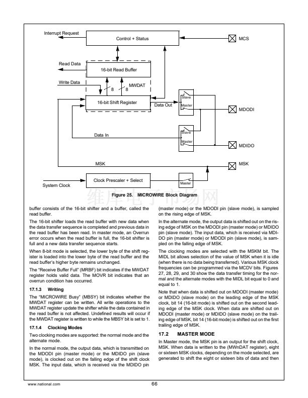
Note that when data is shifted out on MDODI (master mode)
or MDIDO (slave mode) on the leading edge of the MSK
clock, bit 14 (16-bit mode) is shifted out on the second lead-
ing edge of the MSK clock. When data are shifted out on
MDODI (master mode) or MDIDO (slave mode) on the trail-
ing edge of MSK, bit 14 (16-bit mode) is shifted out on the first
trailing edge of MSK.
The 鈥淢ICROWIRE Busy鈥?(MBSY) bit indicates whether the
MWDAT register can be written. All write operations to the
MWDAT register update the shifter while the data contained in
the read buffer is not affected. Undefined results will occur if
the MWDAT register is written to while the MBSY bit is set to 1.
17.1.4
Clocking Modes
Two clocking modes are supported: the normal mode and the
alternate mode.
In the normal mode, the output data, which is transmitted on
the MDODI pin (master mode) or the MDIDO pin (slave
mode), is clocked out on the falling edge of the shift clock
MSK. The input data, which is received via the MDIDO pin
17.2
MASTER MODE
In Master mode, the MSK pin is an output for the shift clock,
MSK. When data is written to the (MWnDAT register), eight
or sixteen MSK clocks, depending on the mode selected, are
generated to shift the eight or sixteen bits of data and then
www.national.com
66


 1
1
 2
2
 3
3
 4
4
 5
5
 6
6
 7
7
 8
8
 9
9
 10
10
 11
11
 12
12
 13
13
 14
14
 15
15
 16
16
 17
17
 18
18
 19
19
 20
20
 21
21
 22
22
 23
23
 24
24
 25
25
 26
26
 27
27
 28
28
 29
29
 30
30
 31
31
 32
32
 33
33
 34
34
 35
35
 36
36
 37
37
 38
38
 39
39
 40
40
 41
41
 42
42
 43
43
 44
44
 45
45
 46
46
 47
47
 48
48
 49
49
 50
50
 51
51
 52
52
 53
53
 54
54
 55
55
 56
56
 57
57
 58
58
 59
59
 60
60
 61
61
 62
62
 63
63
 64
64
 65
65
 66
66
 67
67
 68
68
 69
69
 70
70
 71
71
 72
72
 73
73
 74
74
 75
75
 76
76
 77
77
 78
78
 79
79
 80
80
 81
81
 82
82
 83
83
 84
84
 85
85
 86
86
 87
87
 88
88
 89
89
 90
90
 91
91
 92
92
 93
93
 94
94
 95
95
 96
96
 97
97
 98
98
 99
99
 100
100
 101
101
 102
102
 103
103
 104
104
 105
105
 106
106
 107
107
 108
108
 109
109
 110
110
 111
111
 112
112
 113
113
 114
114
 115
115
 116
116
 117
117
 118
118
 119
119
 120
120
 121
121
 122
122
 123
123
 124
124
 125
125
 126
126
 127
127
 128
128
 129
129
 130
130
 131
131
 132
132
 133
133
 134
134
 135
135
 136
136
 137
137
 138
138
 139
139
 140
140
 141
141
 142
142
 143
143
 144
144
 145
145
 146
146
 147
147
 148
148
 149
149
 150
150
 151
151
 152
152
 153
153
 154
154
 155
155
 156
156
