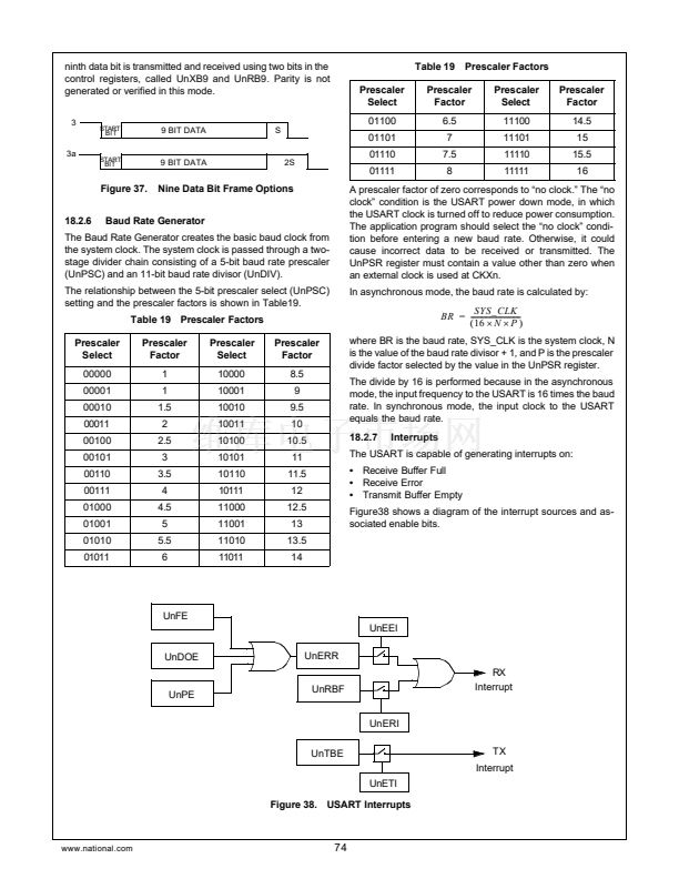
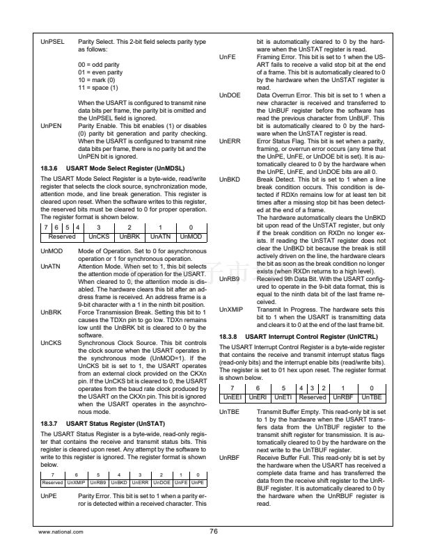
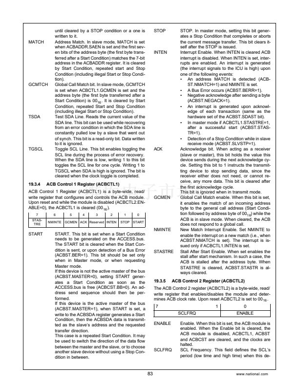
UnETI
UnERI
UnEEI
Enable Transmitter Interrupt. This read/write
bit, when set to 1, enables generation of an in-
terrupt when the hardware sets the UnTBE bit.
Enable Receiver Interrupt. This read/write bit,
when set to 1, enables generation of an inter-
rupt when the hardware sets the UnRBF bit.
Enable Receive Error Interrupt. This read/write
bit, when set to 1, enables generation of an in-
terrupt when the hardware sets the UnERR bit
in the UnSTAT register.
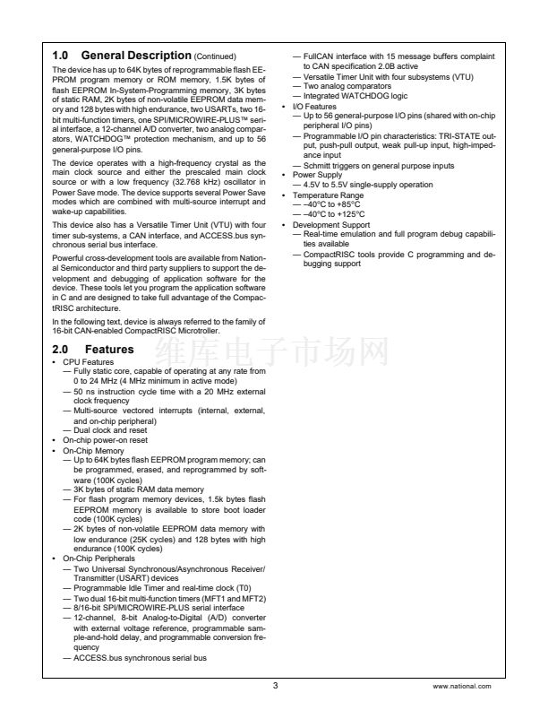
System
Clock
20 MHz
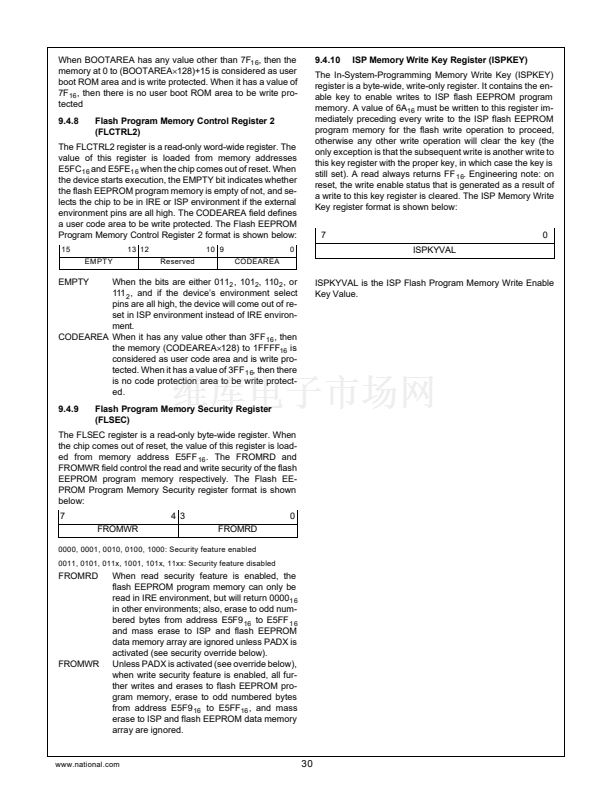
18.4.2
Desired
Baud Rate
19200
N
P
Actual
Baud Rate
19230.769
Percent
Error
0.16
5 13
Baud Rate in Synchronous Mode
The equation for calculating the baud rate in synchronous
mode is:
SYS_CLK
BR
= ----------------------------
(
2
脳
N
脳
P
)
where BR is the baud rate, SYS_CLK is the system clock, N
is the value of the baud rate divisor + 1, and P is the prescaler
divide factor selected by the value in the UnPSR register.
Use the same procedure to determine the values of N and P
as in the asynchronous mode. In this case, however, only in-
teger prescaler values are allowed.
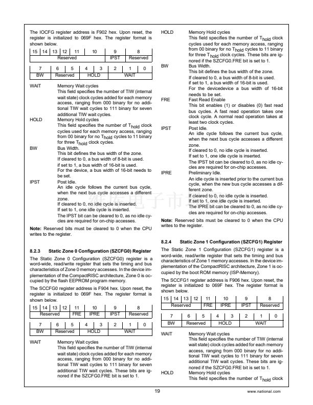
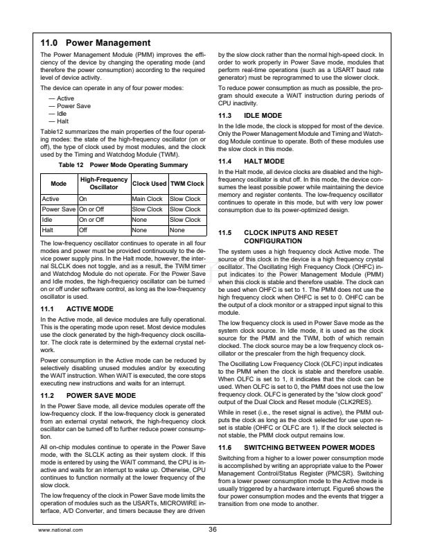
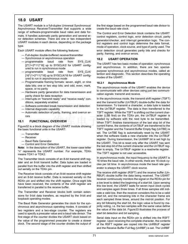
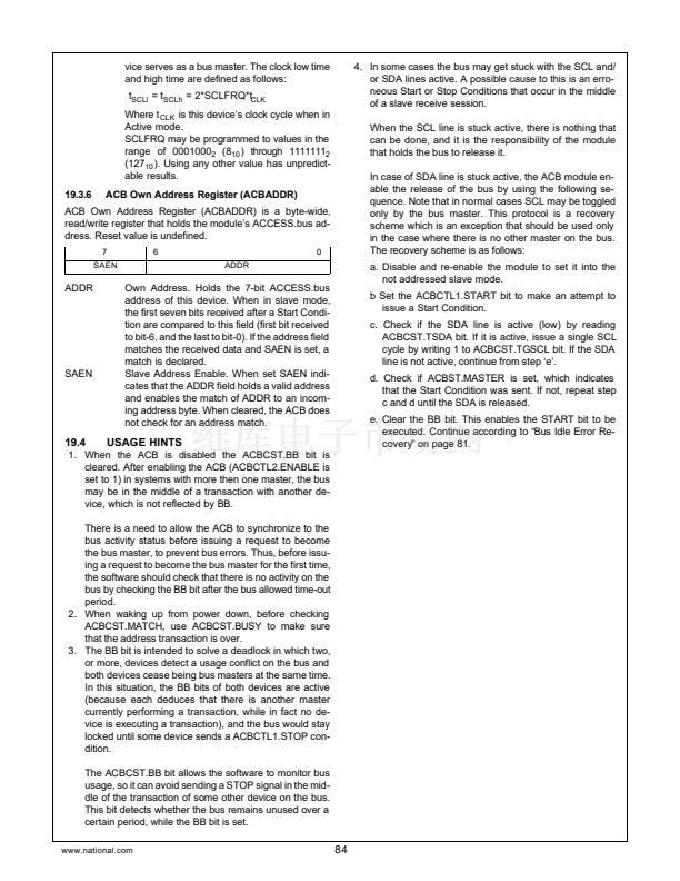
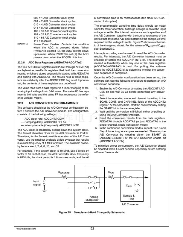
18.4
BAUD RATE CALCULATIONS
The USART baud rate is determined by the system clock fre-
quency and the values programmed into the UnPSR and Un-
BAUD registers. Unless the system clock frequency is an
exact multiple of the desired baud rate, there will be a small
amount of error in the resulting baud rate clock.
The method of baud rate calculation depends on whether the
USART is configured to operate in the asynchronous or syn-
chronous mode.
18.4.1
Baud Rate in Asynchronous Mode
The equation for calculating the baud rate in asynchronous
mode is:
SYS_CLK
BR
= -------------------------------
(
16
脳
N
脳
P
)
where BR is the baud rate, SYS_CLK is the system clock, N
is the value of the baud rate divisor + 1, and P is the prescaler
divide factor selected by the value in the UnPSR register.
Assuming a system clock of 5 MHz and a desired baud rate
of 9600, the NxP term according to the equation above is:
(
5
脳10
6
)
N
脳
P
= ----------------------------- = 32.552
(
16
脳
9600
)
The NxP term is then divided by each Prescaler Factor from
Table 19 to obtain a value closest to an integer. The factor for
this example is 6.5.
32.552
N
= ---------------- = 5.008 (N = 5)
6.5
The baud rate register is programmed with a baud rate divi-
sor of 4 (N = baud rate divisor +1). This produces a baud
clock of:
(
5
脳10 )
BR
= --------------------------------- = 9615.385
(
16
脳
5
脳
6.5
)
%error =
(
9615.385 鈥?9600
)
= 0.16
---------------------------------------------
9600
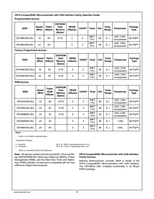
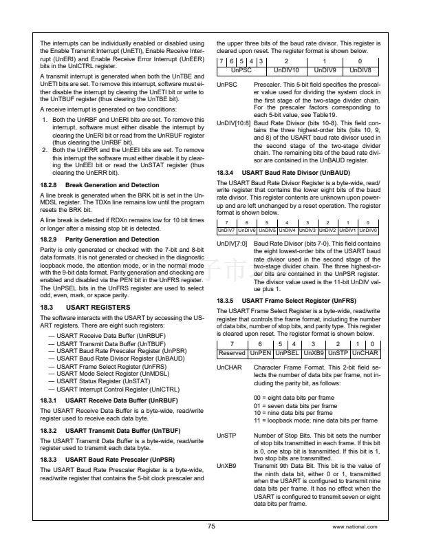
Note that the percent error is much lower than would be pos-
sible without the non-integer prescaler factor. Refer to the ta-
ble below for more examples.
System
Clock
4 MHz
5 MHz
10 MHz
Desired
Baud Rate
9600
9600
19200
N
P
Actual
Baud Rate
9615.385
9615.385
19230.769
Percent
Error
0.16
0.16
0.16
6
2 13
5 6.5
5 6.5
77
www.national.com


 1
1
 2
2
 3
3
 4
4
 5
5
 6
6
 7
7
 8
8
 9
9
 10
10
 11
11
 12
12
 13
13
 14
14
 15
15
 16
16
 17
17
 18
18
 19
19
 20
20
 21
21
 22
22
 23
23
 24
24
 25
25
 26
26
 27
27
 28
28
 29
29
 30
30
 31
31
 32
32
 33
33
 34
34
 35
35
 36
36
 37
37
 38
38
 39
39
 40
40
 41
41
 42
42
 43
43
 44
44
 45
45
 46
46
 47
47
 48
48
 49
49
 50
50
 51
51
 52
52
 53
53
 54
54
 55
55
 56
56
 57
57
 58
58
 59
59
 60
60
 61
61
 62
62
 63
63
 64
64
 65
65
 66
66
 67
67
 68
68
 69
69
 70
70
 71
71
 72
72
 73
73
 74
74
 75
75
 76
76
 77
77
 78
78
 79
79
 80
80
 81
81
 82
82
 83
83
 84
84
 85
85
 86
86
 87
87
 88
88
 89
89
 90
90
 91
91
 92
92
 93
93
 94
94
 95
95
 96
96
 97
97
 98
98
 99
99
 100
100
 101
101
 102
102
 103
103
 104
104
 105
105
 106
106
 107
107
 108
108
 109
109
 110
110
 111
111
 112
112
 113
113
 114
114
 115
115
 116
116
 117
117
 118
118
 119
119
 120
120
 121
121
 122
122
 123
123
 124
124
 125
125
 126
126
 127
127
 128
128
 129
129
 130
130
 131
131
 132
132
 133
133
 134
134
 135
135
 136
136
 137
137
 138
138
 139
139
 140
140
 141
141
 142
142
 143
143
 144
144
 145
145
 146
146
 147
147
 148
148
 149
149
 150
150
 151
151
 152
152
 153
153
 154
154
 155
155
 156
156
