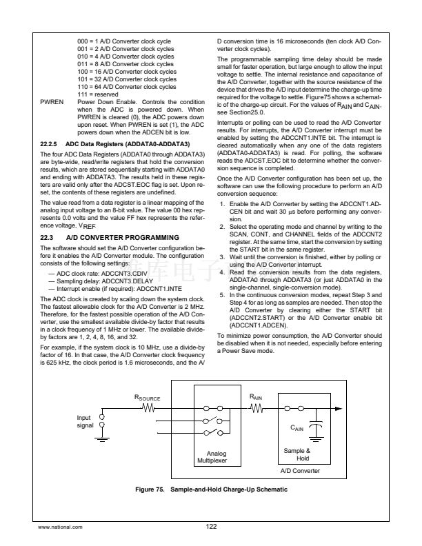
鈥?/div>
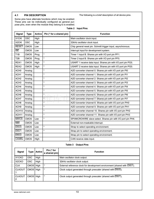
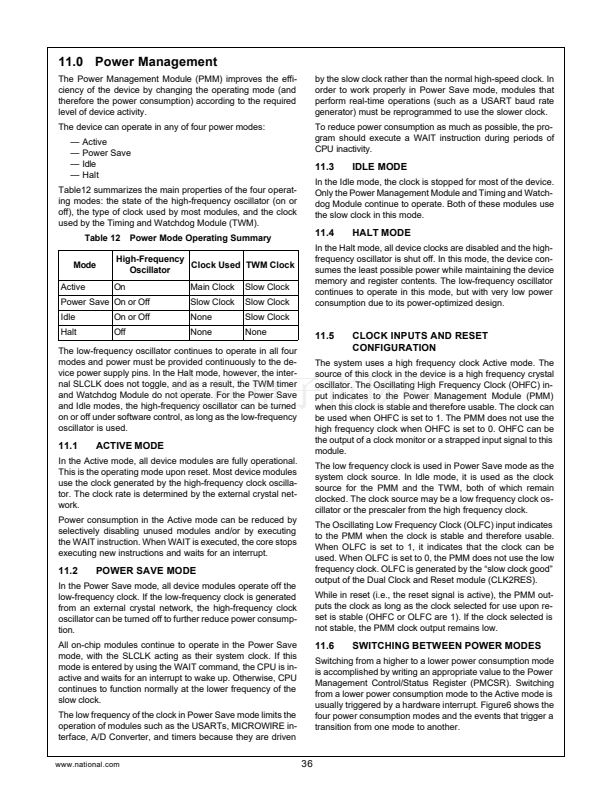
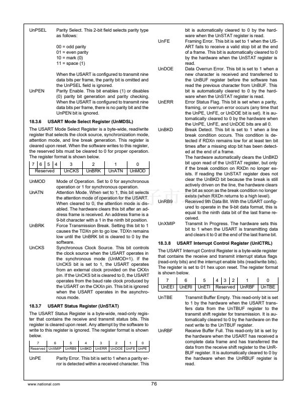
SDA
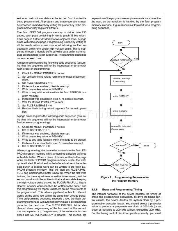
SCL
Data Line
Stable:
Data Valid
Change
of Data
Allowed
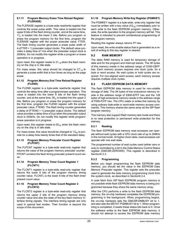
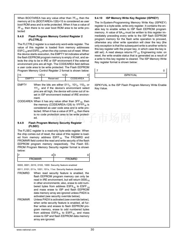
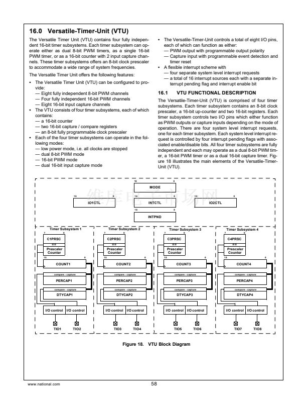
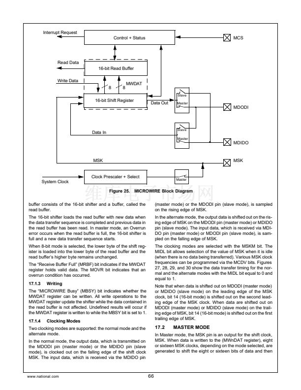
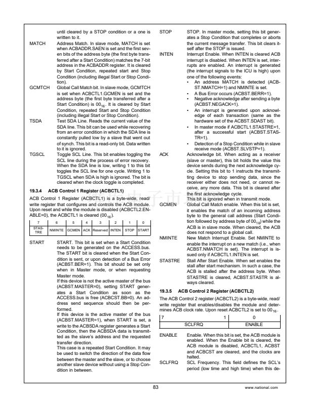
Figure 39. Bit Transfer
Each data transaction is composed of a Start Condition, a
number of byte transfers (set by the software), and a Stop
Condition to terminate the transaction. Each byte is trans-
ferred with the most significant bit first, and after each byte (8
bits), an Acknowledge signal must follow.
At each clock cycle, the slave can stall the master while it
handles the previous data, or prepares new data. This can be
done for each bit transferred or on a byte boundary by the
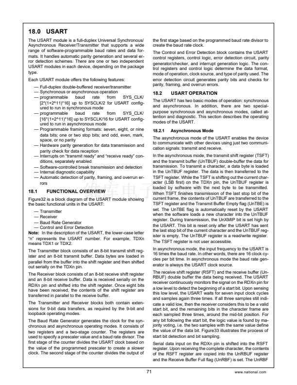
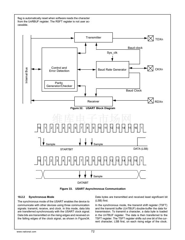
slave holding SCL low to extend the clock-low period. Typi-
cally, slaves extend the first clock cycle of a transfer if a byte
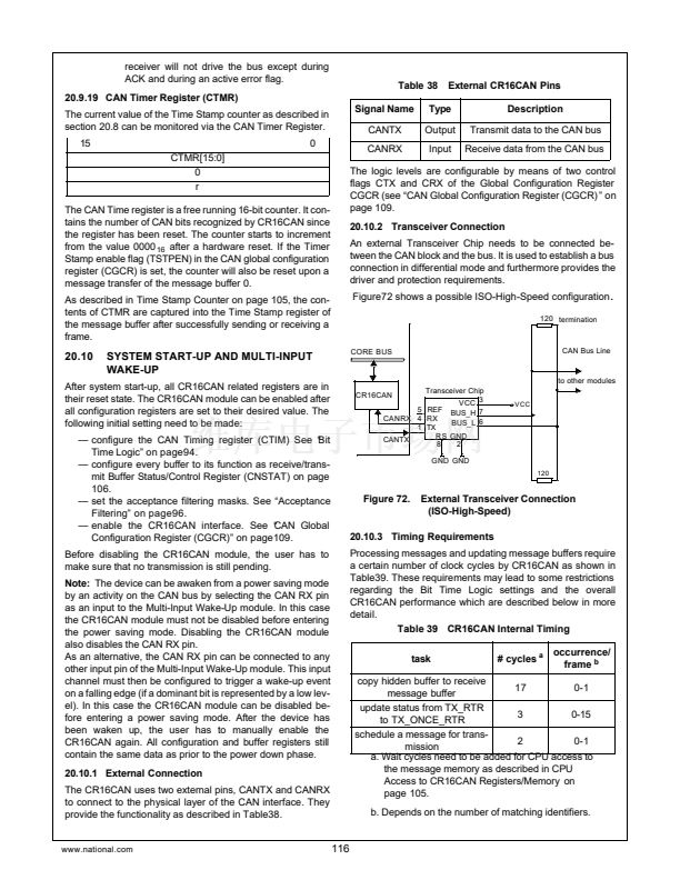
read has not yet been stored, or if the next byte to be trans-
mitted is not yet ready. Some microcontrollers with limited
hardware support for ACESS.bus extend the access after
each bit, thus allowing the software time to handle this bit.
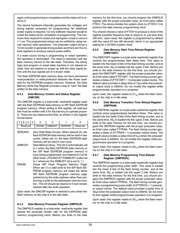
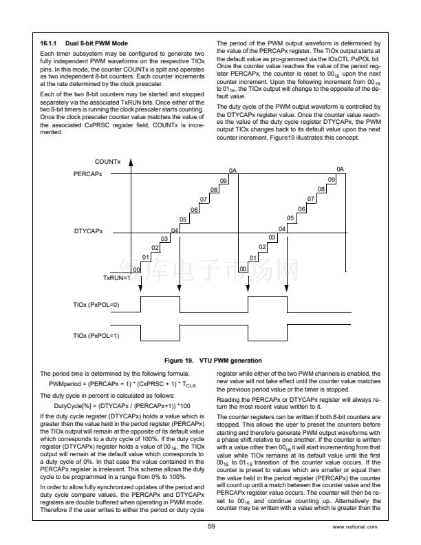
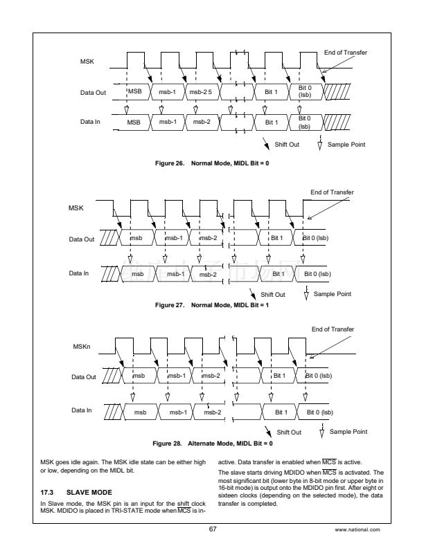
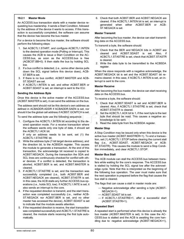
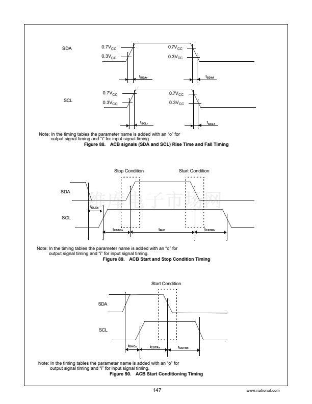
Start and Stop
The ACCESS.bus master generates Start and Stop Condi-
tions (control codes). After a Start Condition is generated the
bus is considered busy and it retains this status until a certain
time after a Stop Condition is generated. A high-to-low tran-
sition of the data line (SDA) while the clock (SCL) is high in-
dicates a Start Condition. A low-to-high transition of the SDA
line while the SCL is high indicates a Stop Condition
(Figure40).
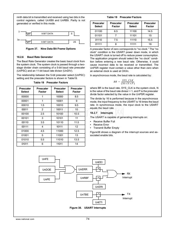
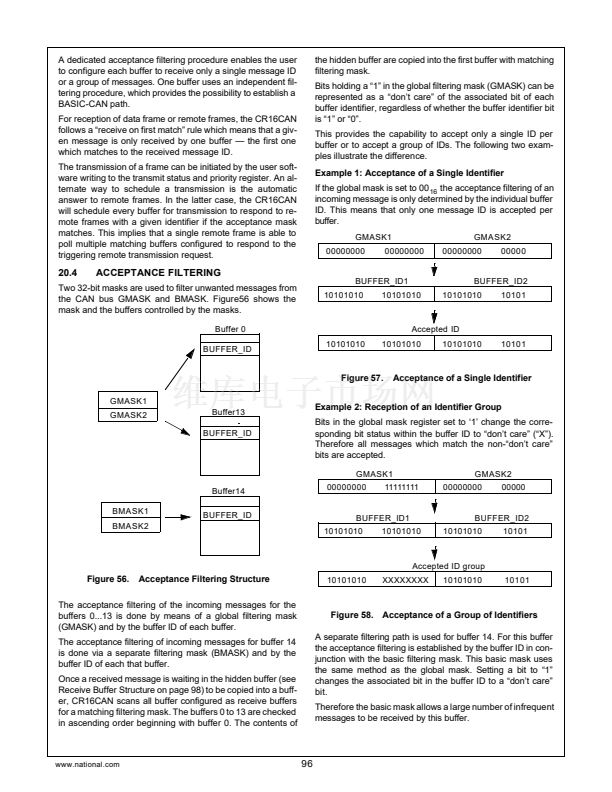
19.1
ACB PROTOCOL OVERVIEW
The ACCESS.bus protocol uses a two-wire interface for bi-
directional communications between the ICs connected to
the bus. The two interface lines are the Serial Data Line
(SDA), and the Serial Clock Line (SCL). These lines should
be connected to a positive supply, via a pull-up resistor, and
remain HIGH even when the bus is idle.
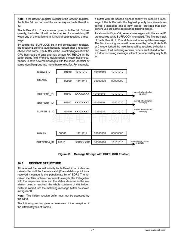
The ACCESS.bus protocol supports multiple master and
slave transmitters and receivers. Each IC has a unique ad-
dress and can operate as a transmitter or a receiver (though
some peripherals are only receivers).
During data transactions, the master device initiates the
transaction, generates the clock signal and terminates the
transaction. For example, when the ACB initiates a data
transaction with an attached ACCESS.bus compliant periph-
eral, the ACB becomes the master. When the peripheral re-
sponds and transmits data to the ACB, their master/slave
(data transaction initiator and clock generator) relationship is
unchanged, even though their transmitter/receiver functions
are reversed.
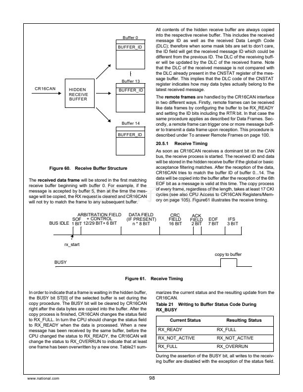
19.1.1
Data Transactions
SDA
One data bit is transferred during each clock pulse. Data is
sampled during the high state of the serial clock (SCL). Con-
sequently, throughout the clock鈥檚 high period, the data should
remain stable (see Figure 39). Any changes on the SDA line
during the high state of the SCL and in the middle of a trans-
action aborts the current transaction. New data should be
sent during the low SCL state. This protocol permits a single
data line to transfer both command/control information and
data using the synchronous serial clock.
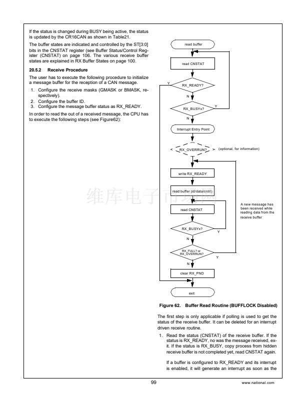
SCL
S
Start
Condition
P
Stop
Condition
Figure 40.
Start and Stop Conditions
In addition to the first Start Condition, a repeated Start Con-
dition can be generated in the middle of a transaction. This
allows another device to be accessed, or a change in the di-
rection of the data transfer.
Acknowledge Cycle
The Acknowledge Cycle consists of two signals: the ac-
knowledge clock pulse the master sends with each byte
www.national.com
78


 1
1
 2
2
 3
3
 4
4
 5
5
 6
6
 7
7
 8
8
 9
9
 10
10
 11
11
 12
12
 13
13
 14
14
 15
15
 16
16
 17
17
 18
18
 19
19
 20
20
 21
21
 22
22
 23
23
 24
24
 25
25
 26
26
 27
27
 28
28
 29
29
 30
30
 31
31
 32
32
 33
33
 34
34
 35
35
 36
36
 37
37
 38
38
 39
39
 40
40
 41
41
 42
42
 43
43
 44
44
 45
45
 46
46
 47
47
 48
48
 49
49
 50
50
 51
51
 52
52
 53
53
 54
54
 55
55
 56
56
 57
57
 58
58
 59
59
 60
60
 61
61
 62
62
 63
63
 64
64
 65
65
 66
66
 67
67
 68
68
 69
69
 70
70
 71
71
 72
72
 73
73
 74
74
 75
75
 76
76
 77
77
 78
78
 79
79
 80
80
 81
81
 82
82
 83
83
 84
84
 85
85
 86
86
 87
87
 88
88
 89
89
 90
90
 91
91
 92
92
 93
93
 94
94
 95
95
 96
96
 97
97
 98
98
 99
99
 100
100
 101
101
 102
102
 103
103
 104
104
 105
105
 106
106
 107
107
 108
108
 109
109
 110
110
 111
111
 112
112
 113
113
 114
114
 115
115
 116
116
 117
117
 118
118
 119
119
 120
120
 121
121
 122
122
 123
123
 124
124
 125
125
 126
126
 127
127
 128
128
 129
129
 130
130
 131
131
 132
132
 133
133
 134
134
 135
135
 136
136
 137
137
 138
138
 139
139
 140
140
 141
141
 142
142
 143
143
 144
144
 145
145
 146
146
 147
147
 148
148
 149
149
 150
150
 151
151
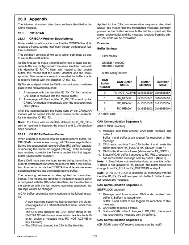 152
152
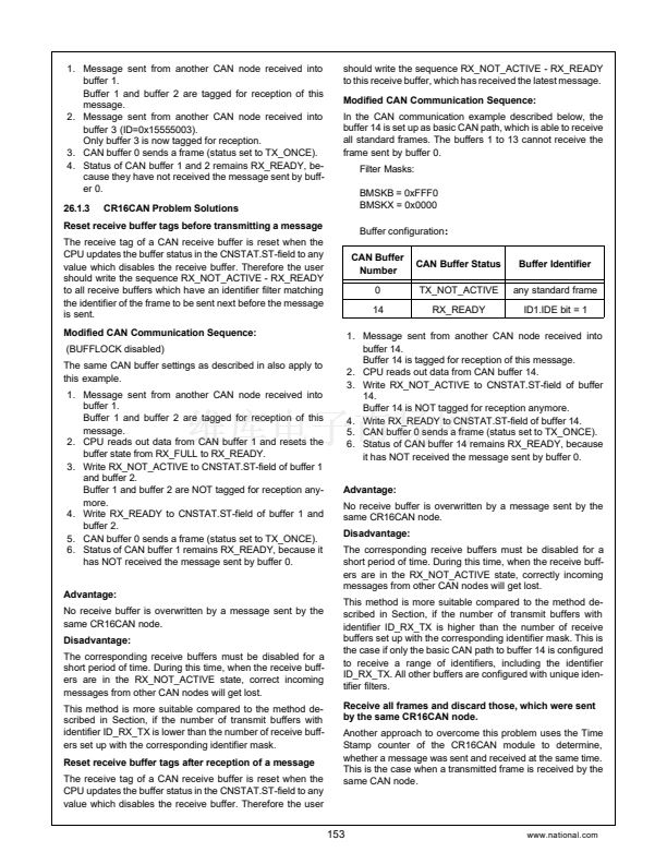 153
153
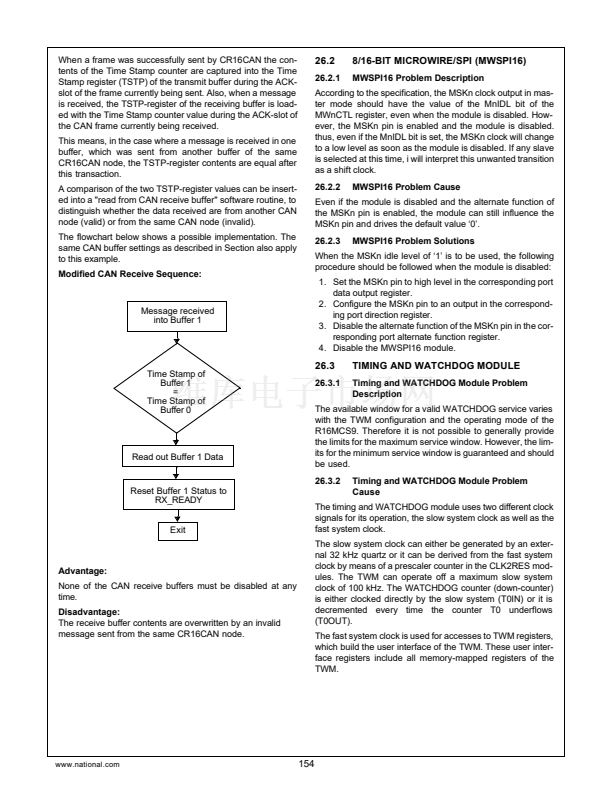 154
154
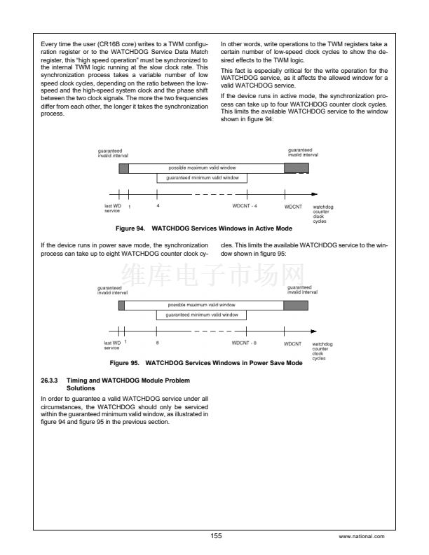 155
155
 156
156
