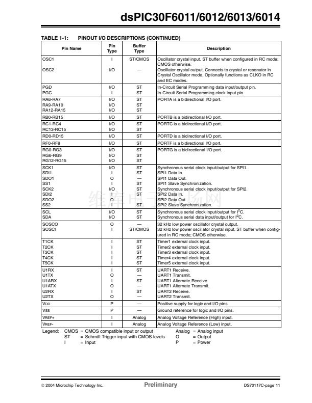
dsPIC30F6011/6012/6013/6014
5.1
Interrupt Priority
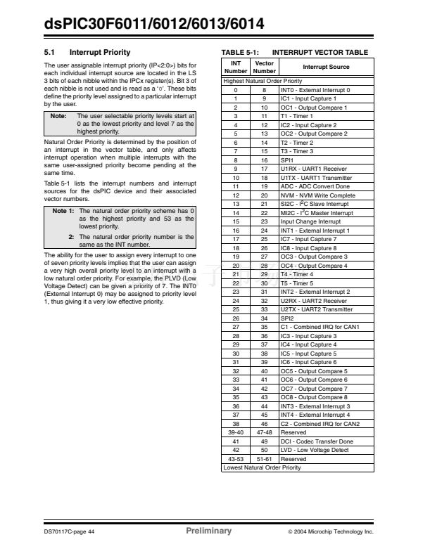
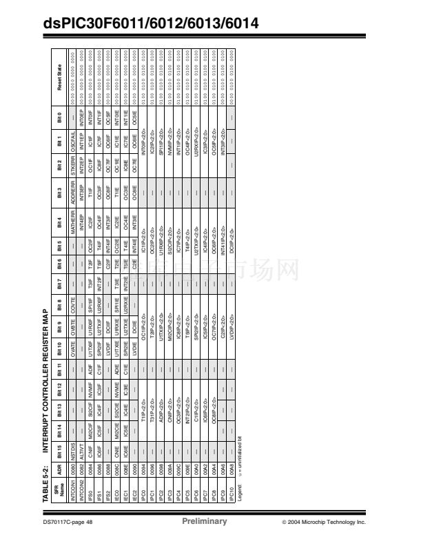
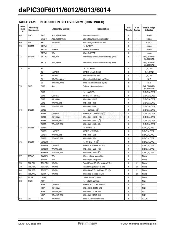
TABLE 5-1:
INT
Number
INTERRUPT VECTOR TABLE
Interrupt Source
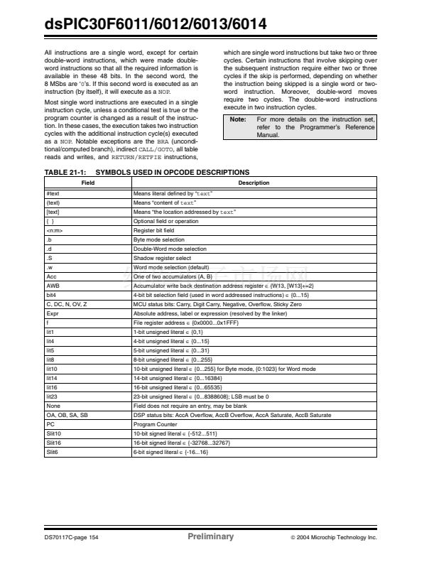
The user assignable interrupt priority (IP<2:0>) bits for
each individual interrupt source are located in the LS
3 bits of each nibble within the IPCx register(s). Bit 3 of
each nibble is not used and is read as a 鈥?鈥? These bits
define the priority level assigned to a particular interrupt
by the user.
Note:
The user selectable priority levels start at
0 as the lowest priority and level 7 as the
highest priority.
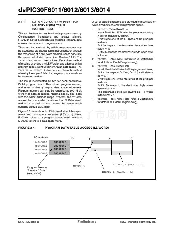
Vector
Number
Highest Natural Order Priority
0
8
INT0 - External Interrupt 0
1
9
IC1 - Input Capture 1
2
10
OC1 - Output Compare 1
T1 - Timer 1
IC2 - Input Capture 2
OC2 - Output Compare 2
T2 - Timer 2
T3 - Timer 3
SPI1
U1RX - UART1 Receiver
U1TX - UART1 Transmitter
ADC - ADC Convert Done
NVM - NVM Write Complete
SI2C - I
2
C Slave Interrupt
14
22
MI2C - I
2
C Master Interrupt
15
23
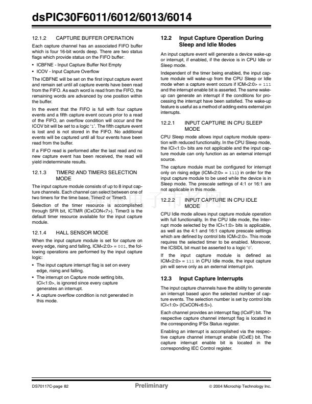
Input Change Interrupt
16
24
INT1 - External Interrupt 1
17
25
IC7 - Input Capture 7
18
26
IC8 - Input Capture 8
19
27
OC3 - Output Compare 3
20
28
OC4 - Output Compare 4
21
29
T4 - Timer 4
22
30
T5 - Timer 5
23
31
INT2 - External Interrupt 2
24
32
U2RX - UART2 Receiver
25
33
U2TX - UART2 Transmitter
26
34
SPI2
27
35
C1 - Combined IRQ for CAN1
28
36
IC3 - Input Capture 3
29
37
IC4 - Input Capture 4
30
38
IC5 - Input Capture 5
31
39
IC6 - Input Capture 6
32
40
OC5 - Output Compare 5
33
41
OC6 - Output Compare 6
34
42
OC7 - Output Compare 7
35
43
OC8 - Output Compare 8
36
44
INT3 - External Interrupt 3
37
45
INT4 - External Interrupt 4
38
46
C2 - Combined IRQ for CAN2
39-40
47-48 Reserved
41
49
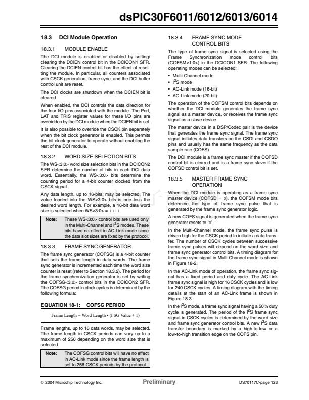
DCI - Codec Transfer Done
42
50
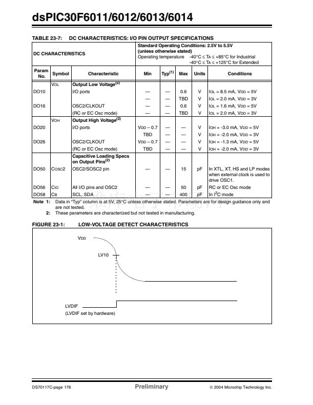
LVD - Low Voltage Detect
43-53
51-61 Reserved
Lowest Natural Order Priority
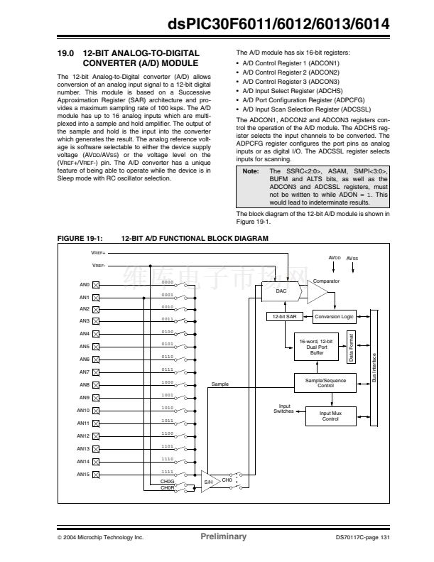
3
4
5
6
7
8
9
10
11
12
13
11
12
13
14
15
16
17
18
19
20
21
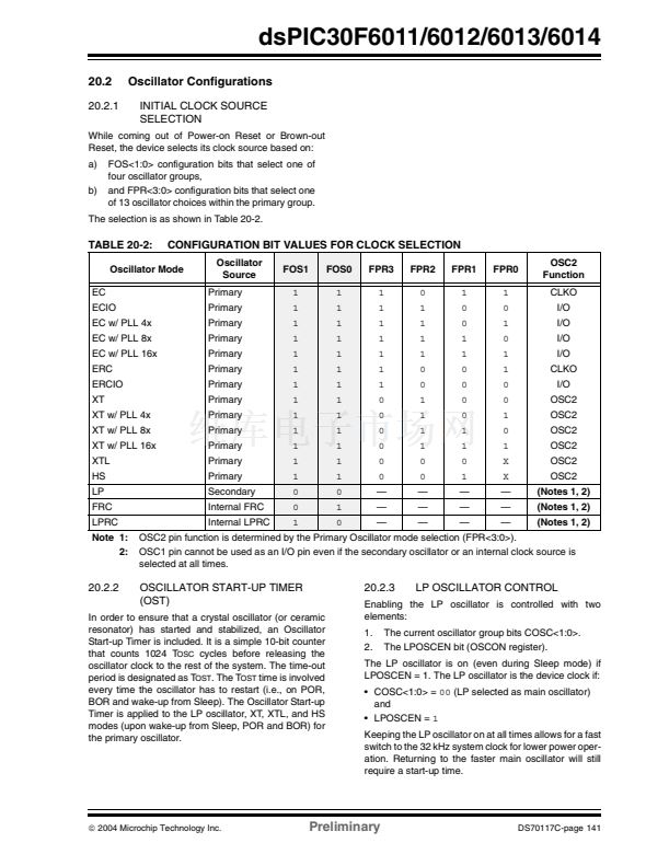
Natural Order Priority is determined by the position of
an interrupt in the vector table, and only affects
interrupt operation when multiple interrupts with the
same user-assigned priority become pending at the
same time.
Table 5-1 lists the interrupt numbers and interrupt
sources for the dsPIC device and their associated
vector numbers.
Note 1:
The natural order priority scheme has 0
as the highest priority and 53 as the
lowest priority.
2:
The natural order priority number is the
same as the INT number.
The ability for the user to assign every interrupt to one
of seven priority levels implies that the user can assign
a very high overall priority level to an interrupt with a
low natural order priority. For example, the PLVD (Low
Voltage Detect) can be given a priority of 7. The INT0
(External Interrupt 0) may be assigned to priority level
1, thus giving it a very low effective priority.
DS70117C-page 44
Preliminary
铮?/div>
2004 Microchip Technology Inc.


 1
1
 2
2
 3
3
 4
4
 5
5
 6
6
 7
7
 8
8
 9
9
 10
10
 11
11
 12
12
 13
13
 14
14
 15
15
 16
16
 17
17
 18
18
 19
19
 20
20
 21
21
 22
22
 23
23
 24
24
 25
25
 26
26
 27
27
 28
28
 29
29
 30
30
 31
31
 32
32
 33
33
 34
34
 35
35
 36
36
 37
37
 38
38
 39
39
 40
40
 41
41
 42
42
 43
43
 44
44
 45
45
 46
46
 47
47
 48
48
 49
49
 50
50
 51
51
 52
52
 53
53
 54
54
 55
55
 56
56
 57
57
 58
58
 59
59
 60
60
 61
61
 62
62
 63
63
 64
64
 65
65
 66
66
 67
67
 68
68
 69
69
 70
70
 71
71
 72
72
 73
73
 74
74
 75
75
 76
76
 77
77
 78
78
 79
79
 80
80
 81
81
 82
82
 83
83
 84
84
 85
85
 86
86
 87
87
 88
88
 89
89
 90
90
 91
91
 92
92
 93
93
 94
94
 95
95
 96
96
 97
97
 98
98
 99
99
 100
100
 101
101
 102
102
 103
103
 104
104
 105
105
 106
106
 107
107
 108
108
 109
109
 110
110
 111
111
 112
112
 113
113
 114
114
 115
115
 116
116
 117
117
 118
118
 119
119
 120
120
 121
121
 122
122
 123
123
 124
124
 125
125
 126
126
 127
127
 128
128
 129
129
 130
130
 131
131
 132
132
 133
133
 134
134
 135
135
 136
136
 137
137
 138
138
 139
139
 140
140
 141
141
 142
142
 143
143
 144
144
 145
145
 146
146
 147
147
 148
148
 149
149
 150
150
 151
151
 152
152
 153
153
 154
154
 155
155
 156
156
 157
157
 158
158
 159
159
 160
160
 161
161
 162
162
 163
163
 164
164
 165
165
 166
166
 167
167
 168
168
 169
169
 170
170
 171
171
 172
172
 173
173
 174
174
 175
175
 176
176
 177
177
 178
178
 179
179
 180
180
 181
181
 182
182
 183
183
 184
184
 185
185
 186
186
 187
187
 188
188
 189
189
 190
190
 191
191
 192
192
 193
193
 194
194
 195
195
 196
196
 197
197
 198
198
 199
199
 200
200
 201
201
 202
202
 203
203
 204
204
 205
205
 206
206
 207
207
 208
208
 209
209
 210
210
 211
211
 212
212
 213
213
 214
214
 215
215
 216
216
 217
217
 218
218
 219
219
 220
220
 221
221
 222
222
