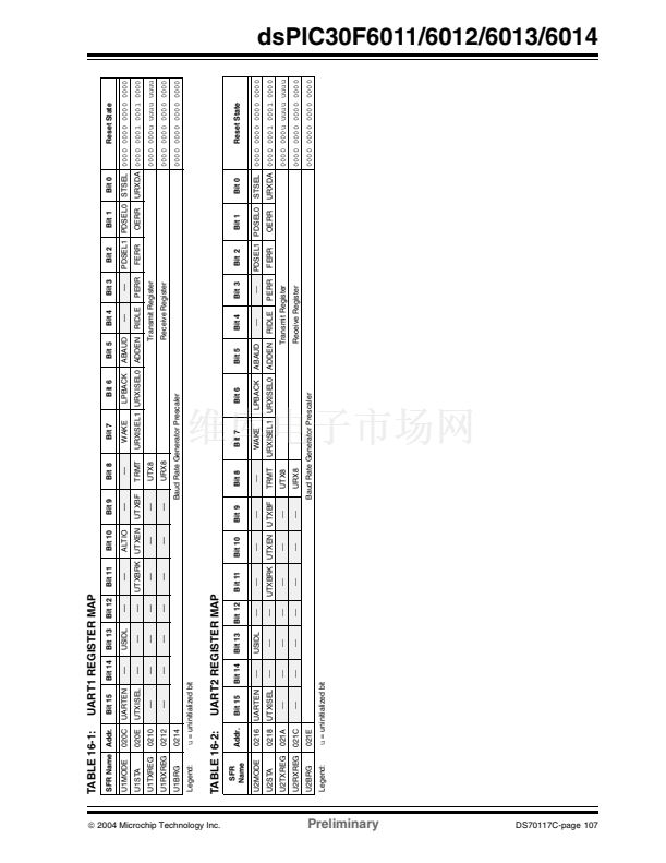
dsPIC30F6011/6012/6013/6014
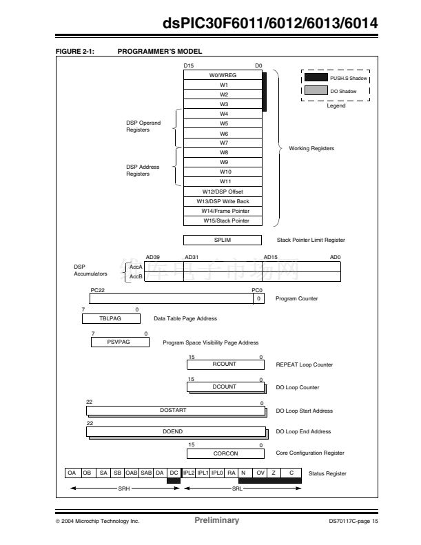
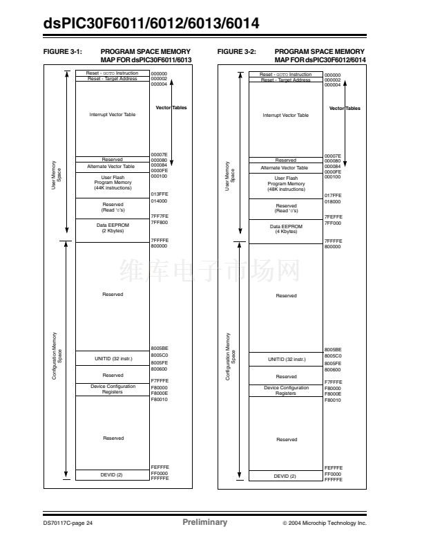
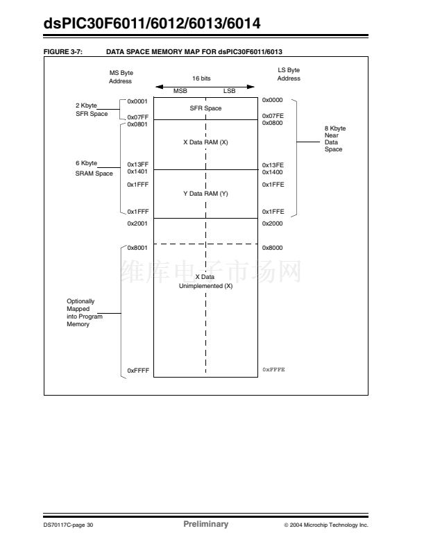
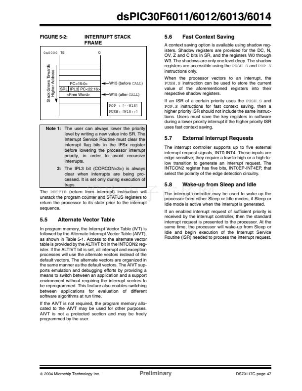
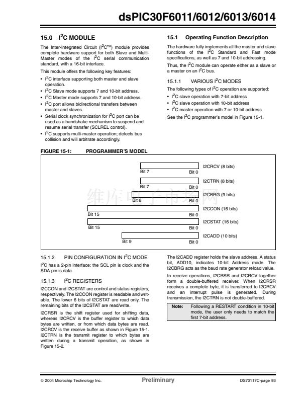
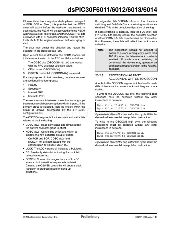
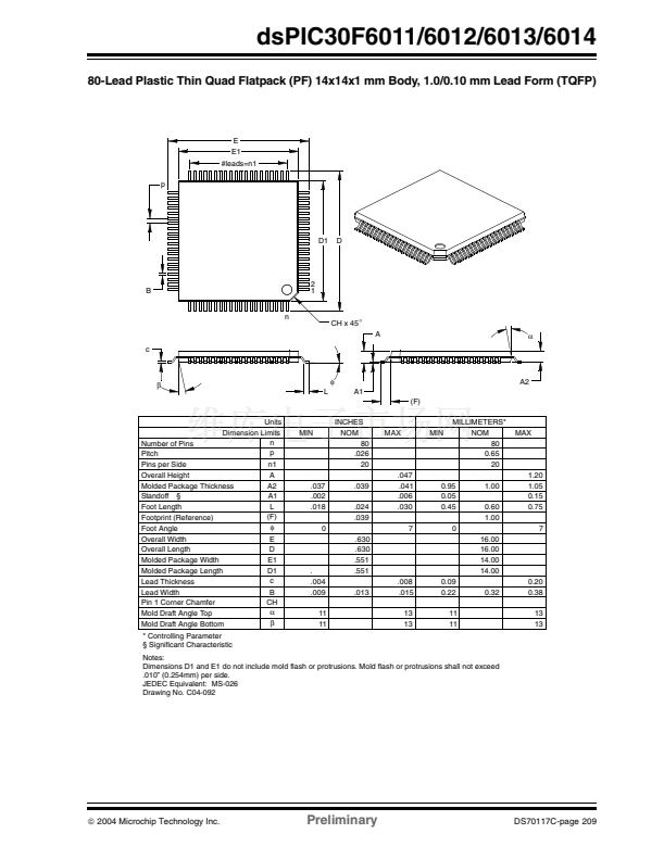
FIGURE 5-2:
0x0000
15
Stack Grows Towards
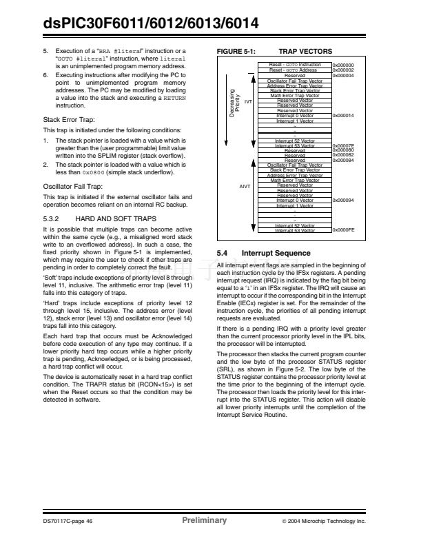
Higher Address
INTERRUPT STACK
FRAME
0
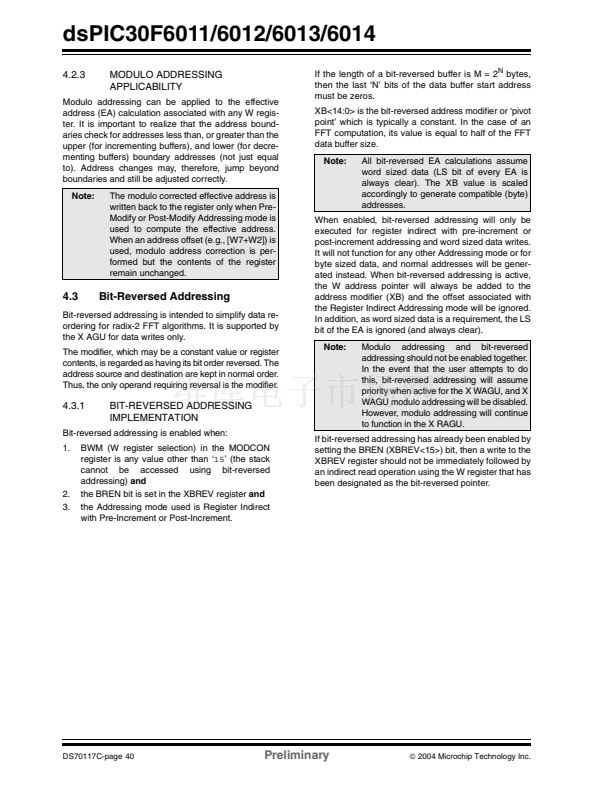
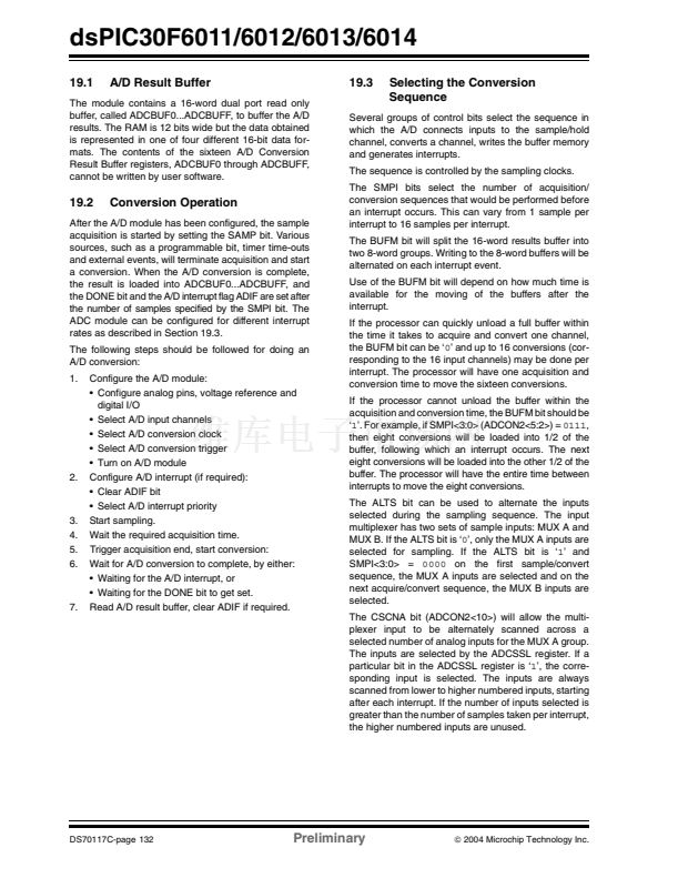
5.6
Fast Context Saving
A context saving option is available using shadow reg-
isters. Shadow registers are provided for the DC, N,
OV, Z and C bits in SR, and the registers W0 through
W3. The shadows are only one level deep. The shadow
registers are accessible using the
PUSH.S
and
POP.S
instructions only.
When the processor vectors to an interrupt, the
PUSH.S
instruction can be used to store the current
value of the aforementioned registers into their
respective shadow registers.
If an ISR of a certain priority uses the
PUSH.S
and
POP.S
instructions for fast context saving, then a
higher priority ISR should not include the same instruc-
tions. Users must save the key registers in software
during a lower priority interrupt if the higher priority ISR
uses fast context saving.
PC<15:0>
SRL IPL3 PC<22:16>
<Free Word>
W15 (before
CALL)
W15 (after
CALL)
POP : [--W15]
PUSH: [W15++]
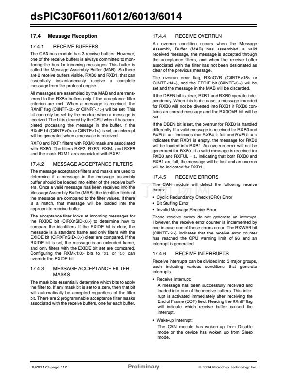
Note 1:
The user can always lower the priority
level by writing a new value into SR. The
Interrupt Service Routine must clear the
interrupt flag bits in the IFSx register
before lowering the processor interrupt
priority, in order to avoid recursive
interrupts.
2:
The IPL3 bit (CORCON<3>) is always
clear when interrupts are being pro-
cessed. It is set only during execution of
traps.
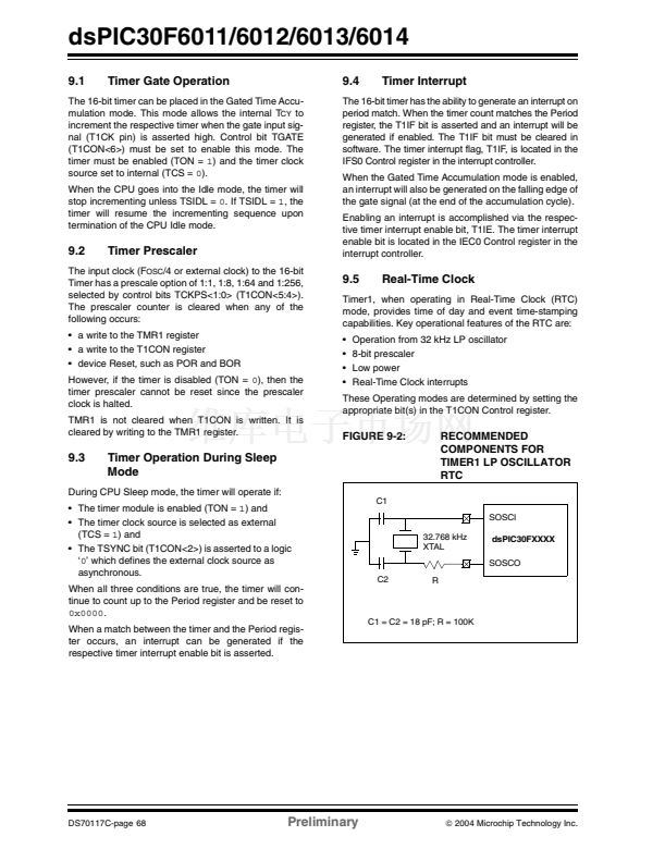
The
RETFIE
(return from interrupt) instruction will
unstack the program counter and STATUS registers to
return the processor to its state prior to the interrupt
sequence.
5.7
External Interrupt Requests
The interrupt controller supports up to five external
interrupt request signals, INT0-INT4. These inputs are
edge sensitive; they require a low-to-high or a high-to-
low transition to generate an interrupt request. The
INTCON2 register has five bits, INT0EP-INT4EP, that
select the polarity of the edge detection circuitry.
5.8
Wake-up from Sleep and Idle
The interrupt controller may be used to wake-up the
processor from either Sleep or Idle modes, if Sleep or
Idle mode is active when the interrupt is generated.
If an enabled interrupt request of sufficient priority is
received by the interrupt controller, then the standard
interrupt request is presented to the processor. At the
same time, the processor will wake-up from Sleep or
Idle and begin execution of the Interrupt Service
Routine (ISR) needed to process the interrupt request.
5.5
Alternate Vector Table
In program memory, the Interrupt Vector Table (IVT) is
followed by the Alternate Interrupt Vector Table (AIVT),
as shown in Table 5-1. Access to the alternate vector
table is provided by the ALTIVT bit in the INTCON2 reg-
ister. If the ALTIVT bit is set, all interrupt and exception
processes will use the alternate vectors instead of the
default vectors. The alternate vectors are organized in
the same manner as the default vectors. The AIVT sup-
ports emulation and debugging efforts by providing a
means to switch between an application and a support
environment without requiring the interrupt vectors to
be reprogrammed. This feature also enables switching
between applications for evaluation of different
software algorithms at run time.
If the AIVT is not required, the program memory allo-
cated to the AIVT may be used for other purposes.
AIVT is not a protected section and may be freely
programmed by the user.
铮?/div>
2004 Microchip Technology Inc.
Preliminary
DS70117C-page 47


 1
1
 2
2
 3
3
 4
4
 5
5
 6
6
 7
7
 8
8
 9
9
 10
10
 11
11
 12
12
 13
13
 14
14
 15
15
 16
16
 17
17
 18
18
 19
19
 20
20
 21
21
 22
22
 23
23
 24
24
 25
25
 26
26
 27
27
 28
28
 29
29
 30
30
 31
31
 32
32
 33
33
 34
34
 35
35
 36
36
 37
37
 38
38
 39
39
 40
40
 41
41
 42
42
 43
43
 44
44
 45
45
 46
46
 47
47
 48
48
 49
49
 50
50
 51
51
 52
52
 53
53
 54
54
 55
55
 56
56
 57
57
 58
58
 59
59
 60
60
 61
61
 62
62
 63
63
 64
64
 65
65
 66
66
 67
67
 68
68
 69
69
 70
70
 71
71
 72
72
 73
73
 74
74
 75
75
 76
76
 77
77
 78
78
 79
79
 80
80
 81
81
 82
82
 83
83
 84
84
 85
85
 86
86
 87
87
 88
88
 89
89
 90
90
 91
91
 92
92
 93
93
 94
94
 95
95
 96
96
 97
97
 98
98
 99
99
 100
100
 101
101
 102
102
 103
103
 104
104
 105
105
 106
106
 107
107
 108
108
 109
109
 110
110
 111
111
 112
112
 113
113
 114
114
 115
115
 116
116
 117
117
 118
118
 119
119
 120
120
 121
121
 122
122
 123
123
 124
124
 125
125
 126
126
 127
127
 128
128
 129
129
 130
130
 131
131
 132
132
 133
133
 134
134
 135
135
 136
136
 137
137
 138
138
 139
139
 140
140
 141
141
 142
142
 143
143
 144
144
 145
145
 146
146
 147
147
 148
148
 149
149
 150
150
 151
151
 152
152
 153
153
 154
154
 155
155
 156
156
 157
157
 158
158
 159
159
 160
160
 161
161
 162
162
 163
163
 164
164
 165
165
 166
166
 167
167
 168
168
 169
169
 170
170
 171
171
 172
172
 173
173
 174
174
 175
175
 176
176
 177
177
 178
178
 179
179
 180
180
 181
181
 182
182
 183
183
 184
184
 185
185
 186
186
 187
187
 188
188
 189
189
 190
190
 191
191
 192
192
 193
193
 194
194
 195
195
 196
196
 197
197
 198
198
 199
199
 200
200
 201
201
 202
202
 203
203
 204
204
 205
205
 206
206
 207
207
 208
208
 209
209
 210
210
 211
211
 212
212
 213
213
 214
214
 215
215
 216
216
 217
217
 218
218
 219
219
 220
220
 221
221
 222
222
