鈥?/div>
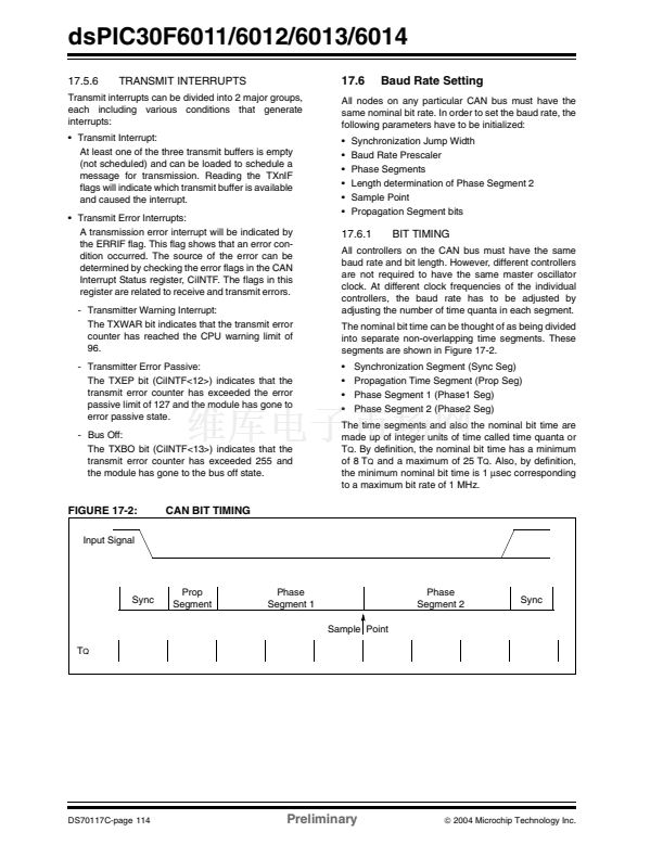
ADC event trigger
Timer gate operation
Selectable prescaler settings
Timer operation during Idle and Sleep modes
Interrupt on a 32-bit period register match
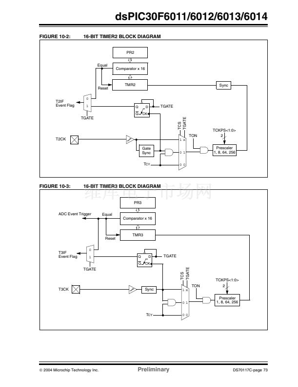
16-bit Timer Mode:
In the 16-bit mode, Timer2 and
Timer3 can be configured as two independent 16-bit
timers. Each timer can be set up in either 16-bit Timer
mode or 16-bit Synchronous Counter mode. See
Section 9.0, Timer1 Module for details on these two
Operating modes.
The only functional difference between Timer2 and
Timer3 is that Timer2 provides synchronization of the
clock prescaler output. This is useful for high frequency
external clock inputs.
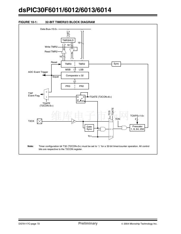
32-bit Timer Mode:
In the 32-bit Timer mode, the timer
increments on every instruction cycle, up to a match
value preloaded into the combined 32-bit Period
register PR3/PR2, then resets to 鈥?鈥?and continues to
count.
For synchronous 32-bit reads of the Timer2/Timer3
pair, reading the LS Word (TMR2 register) will cause
the MS word to be read and latched into a 16-bit
holding register, termed TMR3HLD.
For synchronous 32-bit writes, the holding register
(TMR3HLD) must first be written to. When followed by
a write to the TMR2 register, the contents of TMR3HLD
will be transferred and latched into the MSB of the
32-bit timer (TMR3).
32-bit Synchronous Counter Mode:
In the 32-bit
Synchronous Counter mode, the timer increments on
the rising edge of the applied external clock signal
which is synchronized with the internal phase clocks.
The timer counts up to a match value preloaded in the
combined 32-bit period register PR3/PR2, then resets
to 鈥?鈥?and continues.
When the timer is configured for the Synchronous
Counter mode of operation and the CPU goes into the
Idle mode, the timer will stop incrementing unless the
TSIDL (T2CON<13>) bit =
0.
If TSIDL =
1,
the timer
module logic will resume the incrementing sequence
upon termination of the CPU Idle mode.
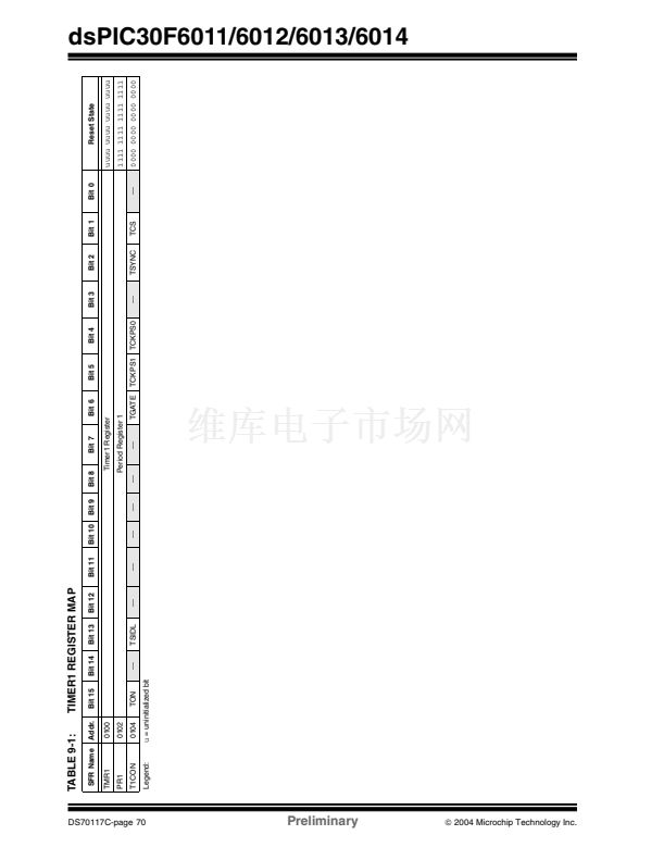
These Operating modes are determined by setting the
appropriate bit(s) in the 16-bit T2CON and T3CON
SFRs.
For 32-bit timer/counter operation, Timer2 is the LS
Word and Timer3 is the MS Word of the 32-bit timer.
Note:
For 32-bit timer operation, T3CON control
bits are ignored. Only T2CON control bits
are used for setup and control. Timer2
clock and gate inputs are utilized for the
32-bit timer module but an interrupt is gen-
erated with the Timer3 interrupt flag (T3IF)
and the interrupt is enabled with the
Timer3 interrupt enable bit (T3IE).
铮?/div>
2004 Microchip Technology Inc.
Preliminary
DS70117C-page 71


 1
1
 2
2
 3
3
 4
4
 5
5
 6
6
 7
7
 8
8
 9
9
 10
10
 11
11
 12
12
 13
13
 14
14
 15
15
 16
16
 17
17
 18
18
 19
19
 20
20
 21
21
 22
22
 23
23
 24
24
 25
25
 26
26
 27
27
 28
28
 29
29
 30
30
 31
31
 32
32
 33
33
 34
34
 35
35
 36
36
 37
37
 38
38
 39
39
 40
40
 41
41
 42
42
 43
43
 44
44
 45
45
 46
46
 47
47
 48
48
 49
49
 50
50
 51
51
 52
52
 53
53
 54
54
 55
55
 56
56
 57
57
 58
58
 59
59
 60
60
 61
61
 62
62
 63
63
 64
64
 65
65
 66
66
 67
67
 68
68
 69
69
 70
70
 71
71
 72
72
 73
73
 74
74
 75
75
 76
76
 77
77
 78
78
 79
79
 80
80
 81
81
 82
82
 83
83
 84
84
 85
85
 86
86
 87
87
 88
88
 89
89
 90
90
 91
91
 92
92
 93
93
 94
94
 95
95
 96
96
 97
97
 98
98
 99
99
 100
100
 101
101
 102
102
 103
103
 104
104
 105
105
 106
106
 107
107
 108
108
 109
109
 110
110
 111
111
 112
112
 113
113
 114
114
 115
115
 116
116
 117
117
 118
118
 119
119
 120
120
 121
121
 122
122
 123
123
 124
124
 125
125
 126
126
 127
127
 128
128
 129
129
 130
130
 131
131
 132
132
 133
133
 134
134
 135
135
 136
136
 137
137
 138
138
 139
139
 140
140
 141
141
 142
142
 143
143
 144
144
 145
145
 146
146
 147
147
 148
148
 149
149
 150
150
 151
151
 152
152
 153
153
 154
154
 155
155
 156
156
 157
157
 158
158
 159
159
 160
160
 161
161
 162
162
 163
163
 164
164
 165
165
 166
166
 167
167
 168
168
 169
169
 170
170
 171
171
 172
172
 173
173
 174
174
 175
175
 176
176
 177
177
 178
178
 179
179
 180
180
 181
181
 182
182
 183
183
 184
184
 185
185
 186
186
 187
187
 188
188
 189
189
 190
190
 191
191
 192
192
 193
193
 194
194
 195
195
 196
196
 197
197
 198
198
 199
199
 200
200
 201
201
 202
202
 203
203
 204
204
 205
205
 206
206
 207
207
 208
208
 209
209
 210
210
 211
211
 212
212
 213
213
 214
214
 215
215
 216
216
 217
217
 218
218
 219
219
 220
220
 221
221
 222
222
