P R E L I M I N A R Y
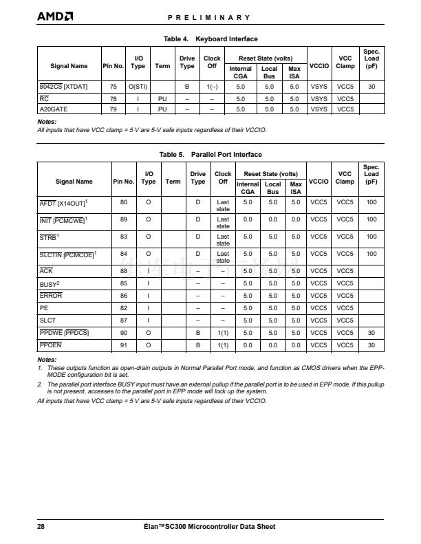
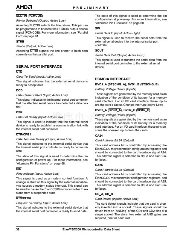
SLCTIN [PCMCOE]
The state of this signal is used to determine the pin
configuration at power-up. For more information, see
鈥淎lternate Pin Functions鈥?on page 68.
SIN
Printer Selected (Output; Active Low)
Asserting SLCTIN selects the line printer. This pin can
be programmed to become the PCMCIA output enable
signal (PCMCOE). For more information, see 鈥淧arallel
Port鈥?on page 61.
STRB
Serial Data In (Input; Active High)
This signal is used to receive the serial data from the
external serial device into the internal serial port
controller.
SOUT
Strobe (Output; Active Low)
Asserting STRB signals the line printer to latch data
currently on the parallel port.
Serial Data Out (Output; Active High)
This signal is used to transmit the serial data from the
internal serial port controller to the external serial
device.
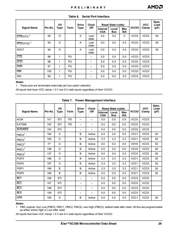
SERIAL PORT INTERFACE
CTS
Clear To Send (Input; Active Low)
This signal indicates that the external serial device is
ready to accept data.
DCD
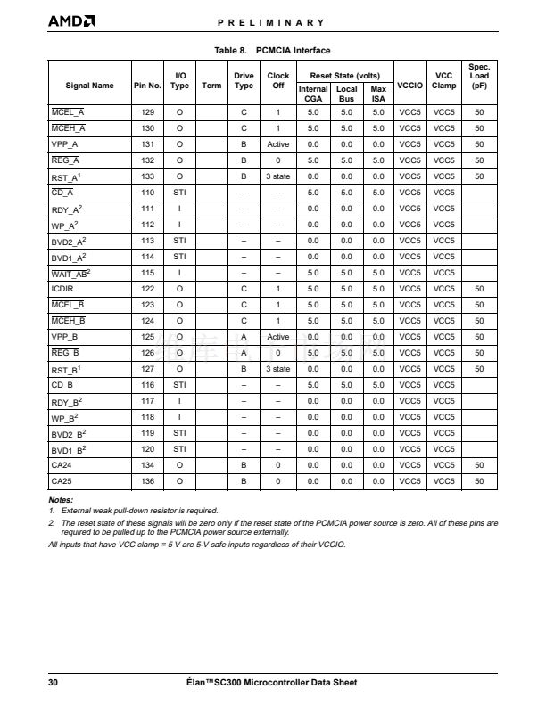
PCMCIA INTERFACE
BVD1_A (STSCHG_A), BVD1_B (STSCHG_B)
Battery Voltage Detect (Inputs)
These signals are generated by the memory card as an
indication of the condition of its battery for a memory
card interface. For an I/O card interface, these inputs
are the card鈥檚 Status Change Interrupt (active Low).
BVD2_A (SPKR_A), BVD2_B (SPKR_B)
Data Carrier Detect (Input; Active Low)
This signal indicates to the internal serial port controller
that the attached serial device has detected a data car-
rier.
DSR
Data Set Ready (Input; Active Low)
This signal is used to indicate that the external serial
device is ready to establish a communication link with
the internal serial port controller.
DTR/CFG1
Battery Voltage Detect (Inputs)
These signals are generated by the memory card as an
indication of the condition of its battery for a memory
card interface. For an I/O card interface, these pins be-
come the speaker inputs from the cards.
CA24
Data Terminal Ready (Output; Active Low)
This signal indicates to the external serial device that
the internal serial port controller is ready to communi-
cate.
The state of this signal is used to determine the pin
configuration at power-up. For more information, see
鈥淎lternate Pin Functions鈥?on page 68.
RIN
Card Address Bit 24 (Output)
This card address bit is controlled by accessing the
脡lanSC300 microcontroller configuration registers and
should be connected to the card interface signal A24.
This address signal is common to slot A and slot B in-
terfaces.
CA25
Card Address Bit 25 (Output)
This card address bit is controlled by accessing the
脡lanSC300 microcontroller configuration registers, and
should be connected to the card interface signal A25.
This address signal is common to slot A and slot B in-
terfaces.
CD_A, CD_B
Ring Indicate (Input; Active Low)
This signal is used as a modem control function. A
change in state on this signal by the external serial de-
vice causes a modem status interrupt. This signal can
be used to cause the 脡lanSC300 microcontroller to re-
sume from a suspended state.
RTS/CFG0
Card Detect (Inputs; Active Low)
The card detect signals indicate that the card is prop-
erly inserted into a socket. These signals should be
driven from an 鈥淎NDing鈥?of the CD1 and CD2 pins of a
single socket. Therefore, two external AND gates are
required, one for each slot.
Request To Send (Output; Active Low)
This signal indicates to the external serial device that
the internal serial port controller is ready to send data.
38
脡lan鈩C300 Microcontroller Data Sheet


 1
1
 2
2
 3
3
 4
4
 5
5
 6
6
 7
7
 8
8
 9
9
 10
10
 11
11
 12
12
 13
13
 14
14
 15
15
 16
16
 17
17
 18
18
 19
19
 20
20
 21
21
 22
22
 23
23
 24
24
 25
25
 26
26
 27
27
 28
28
 29
29
 30
30
 31
31
 32
32
 33
33
 34
34
 35
35
 36
36
 37
37
 38
38
 39
39
 40
40
 41
41
 42
42
 43
43
 44
44
 45
45
 46
46
 47
47
 48
48
 49
49
 50
50
 51
51
 52
52
 53
53
 54
54
 55
55
 56
56
 57
57
 58
58
 59
59
 60
60
 61
61
 62
62
 63
63
 64
64
 65
65
 66
66
 67
67
 68
68
 69
69
 70
70
 71
71
 72
72
 73
73
 74
74
 75
75
 76
76
 77
77
 78
78
 79
79
 80
80
 81
81
 82
82
 83
83
 84
84
 85
85
 86
86
 87
87
 88
88
 89
89
 90
90
 91
91
 92
92
 93
93
 94
94
 95
95
 96
96
 97
97
 98
98
 99
99
 100
100
 101
101
 102
102
 103
103
 104
104
 105
105
 106
106
 107
107
 108
108
 109
109
 110
110
 111
111
 112
112
 113
113
 114
114
 115
115
 116
116
 117
117
 118
118
 119
119
 120
120
 121
121
 122
122
 123
123
 124
124
 125
125
 126
126
 127
127
 128
128
 129
129
 130
130
 131
131
 132
132
 133
133
 134
134
 135
135
 136
136
 137
137
 138
138
 139
139
