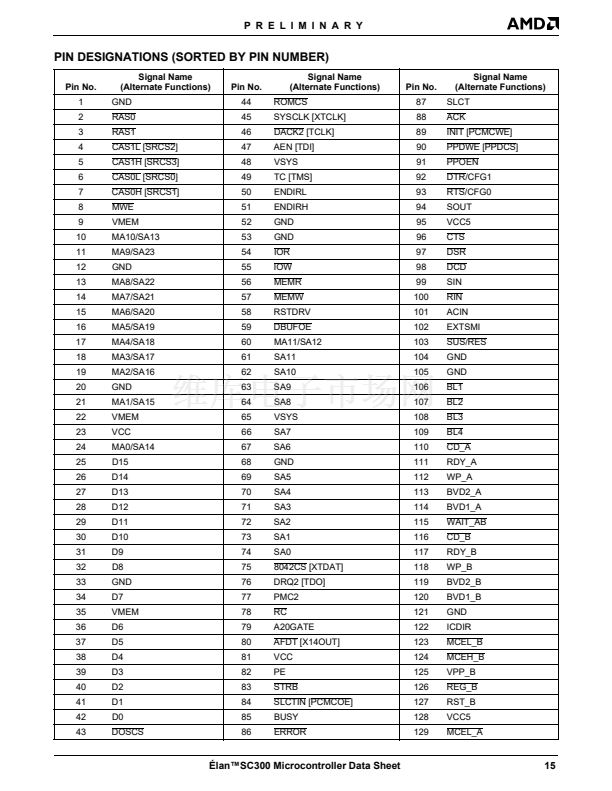
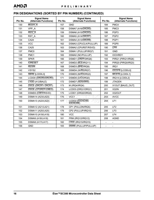
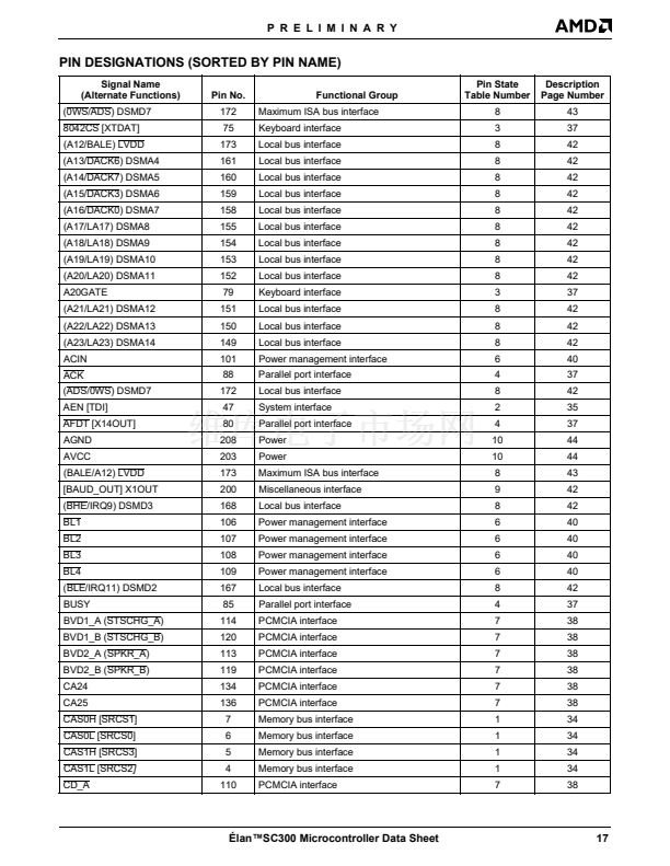
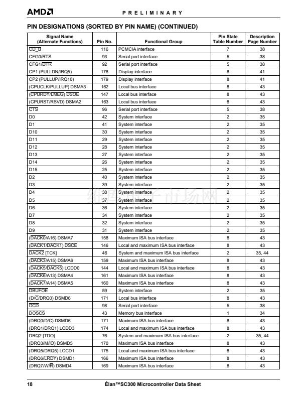
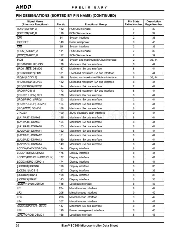
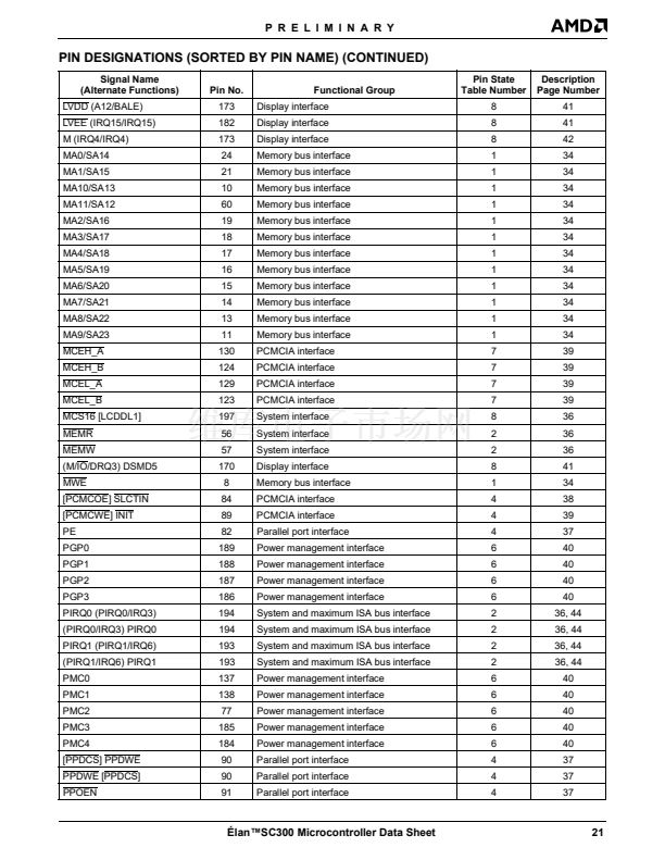
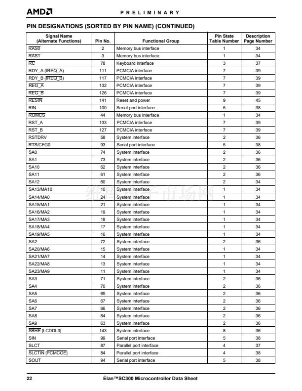
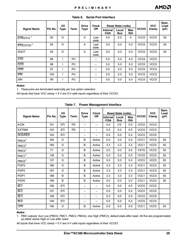
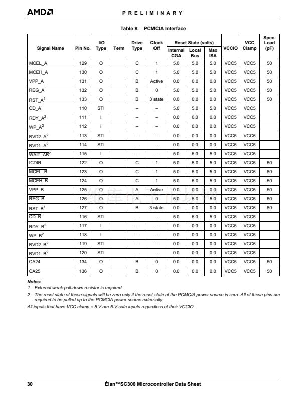
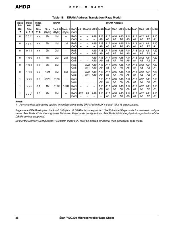
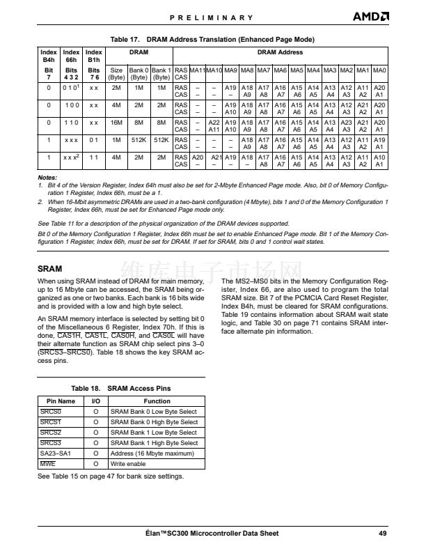
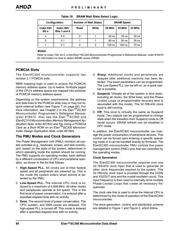
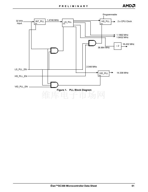
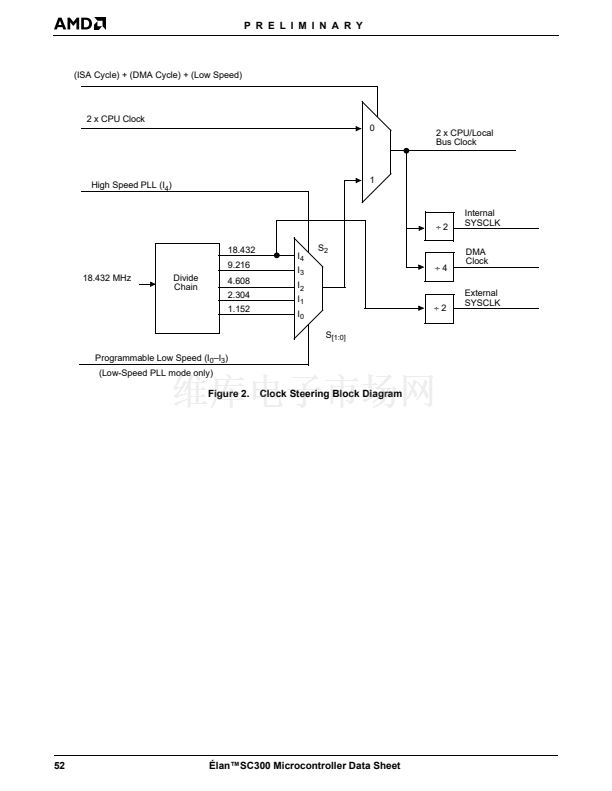
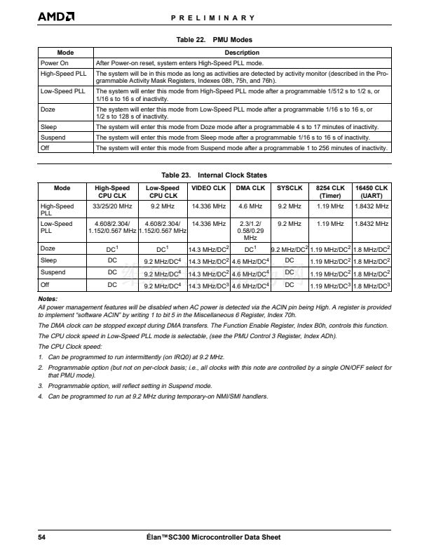
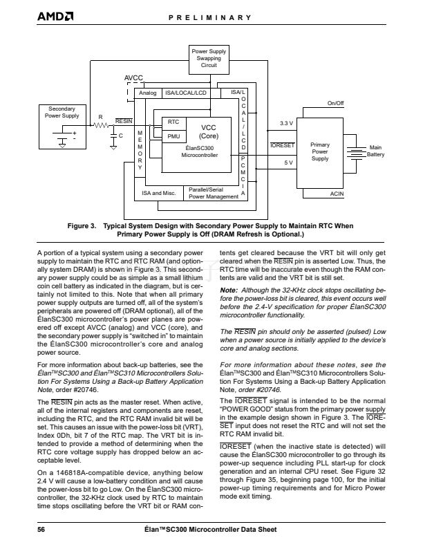
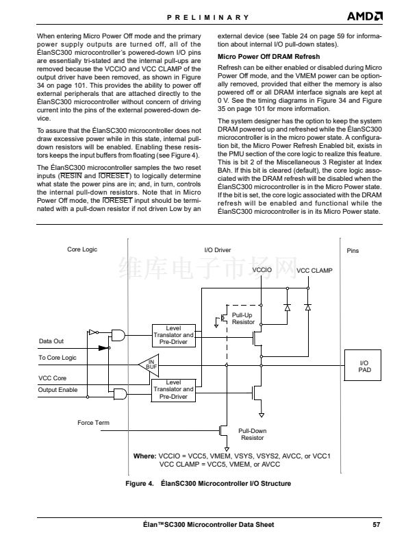
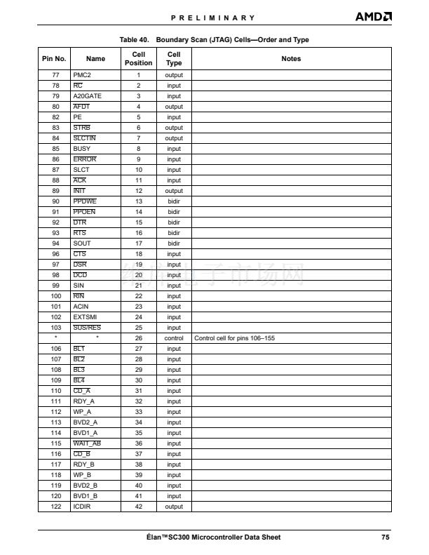
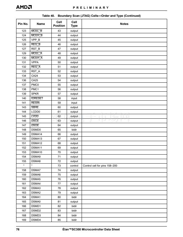
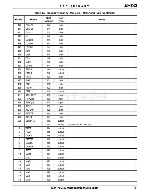
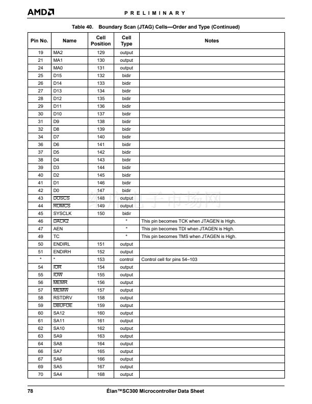
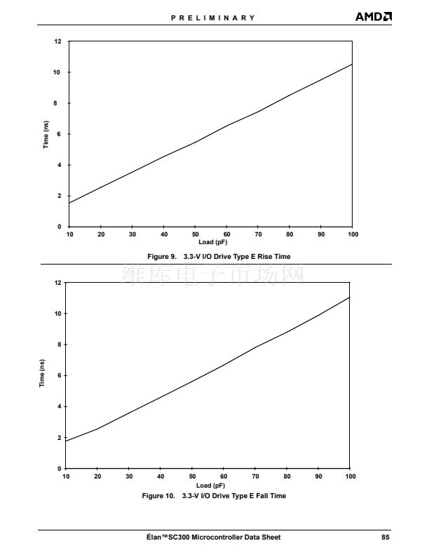
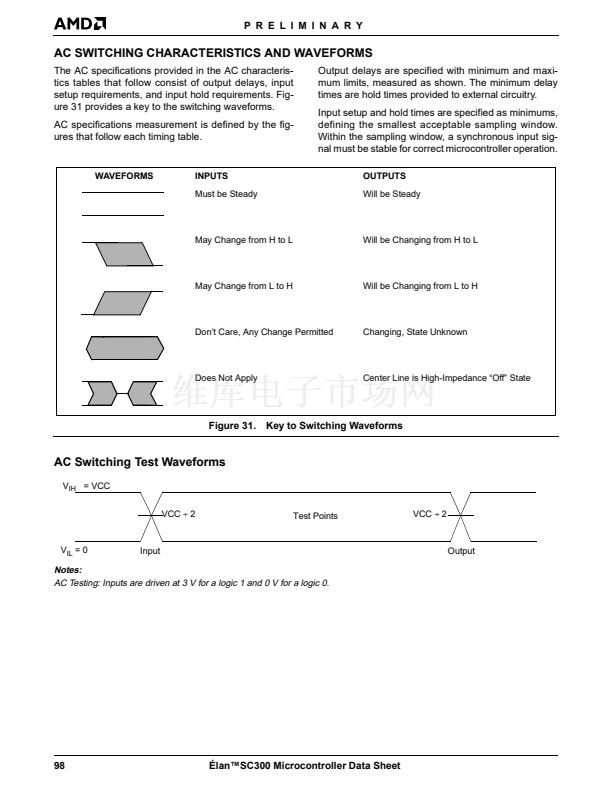
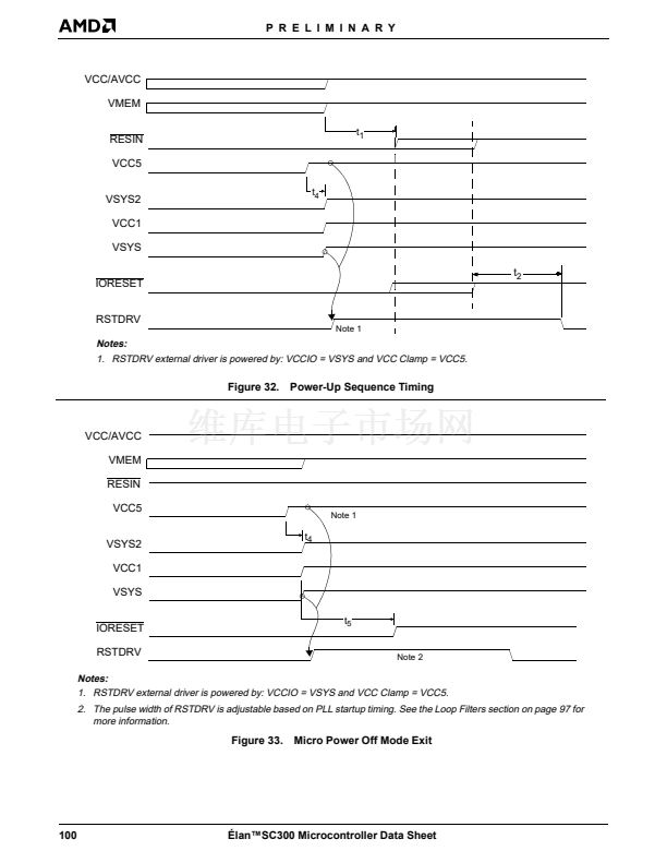
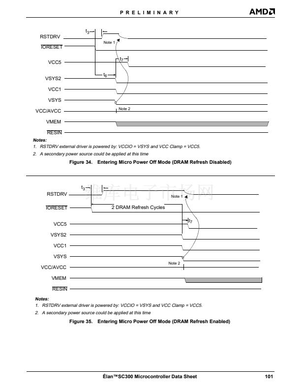
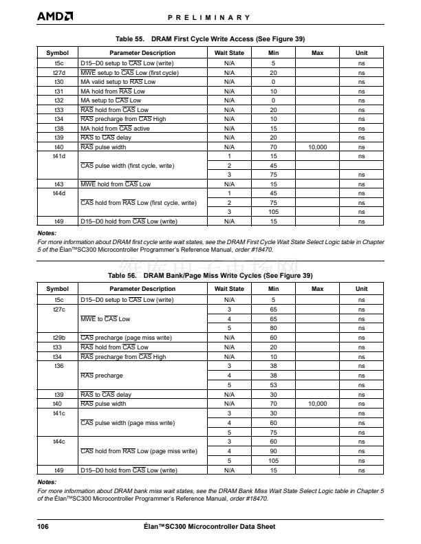
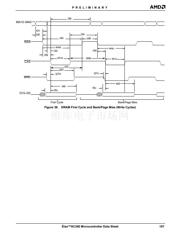
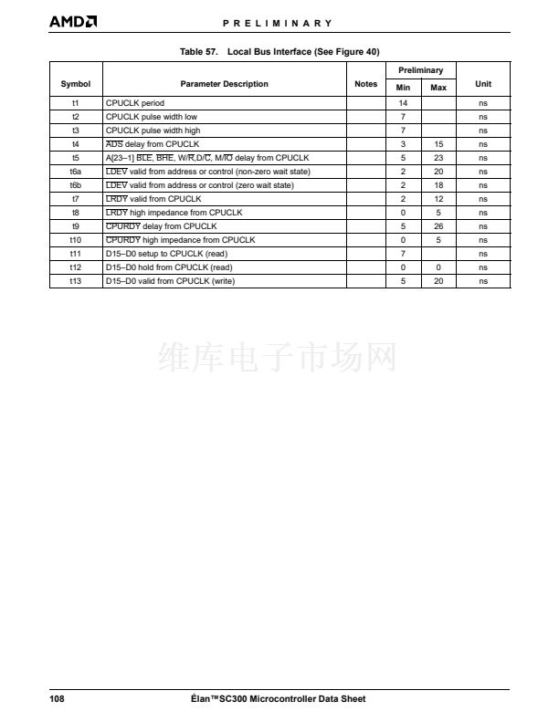
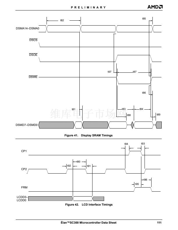
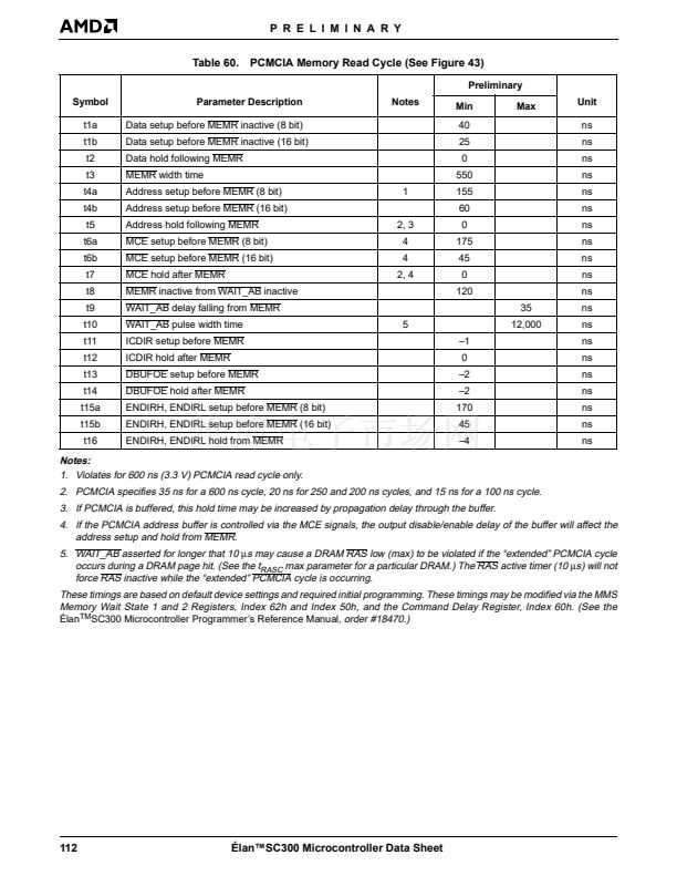
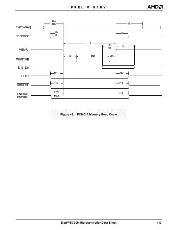
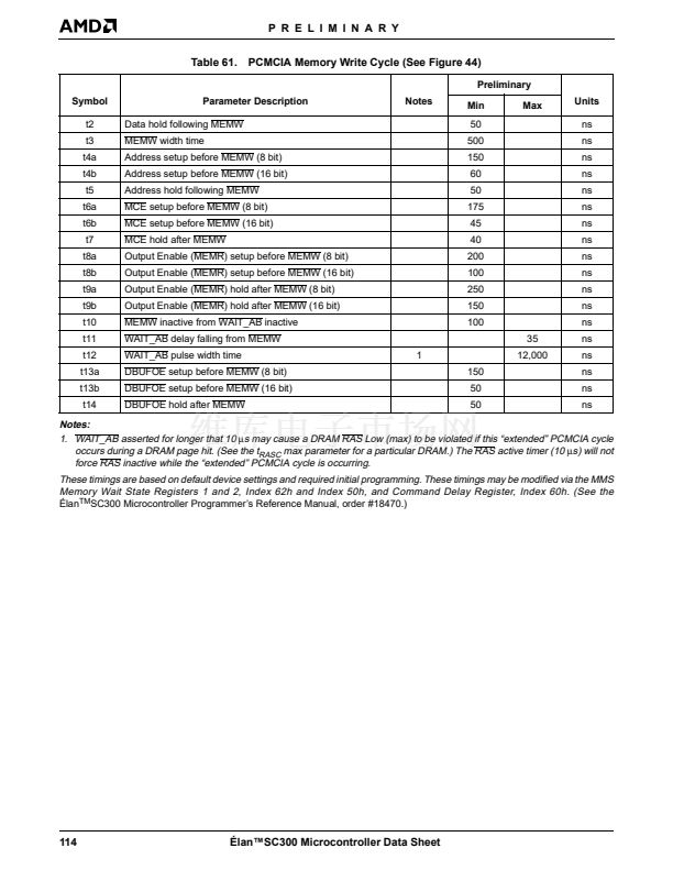
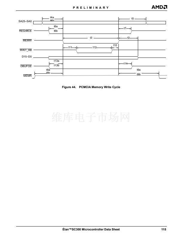
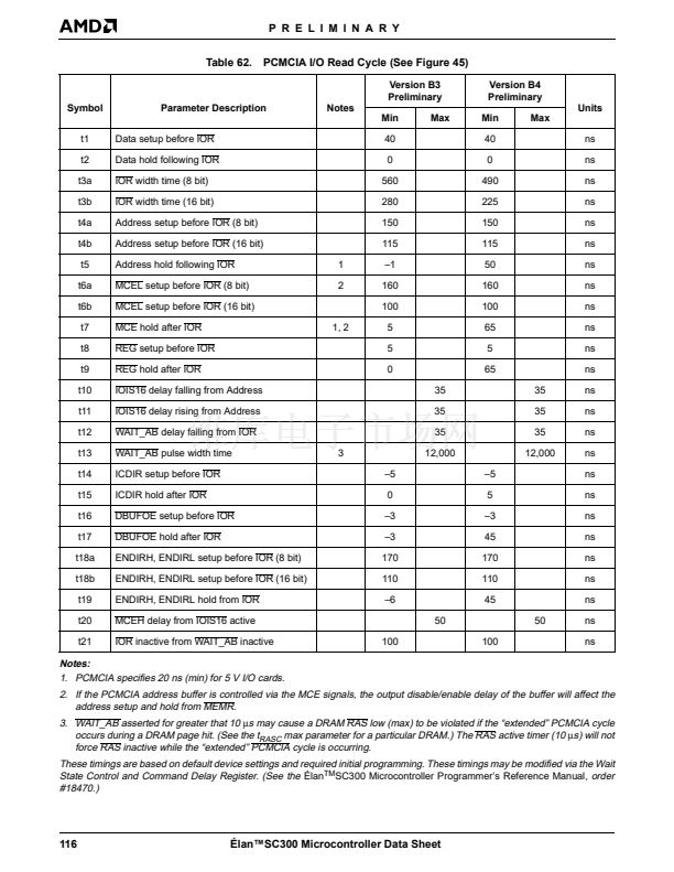
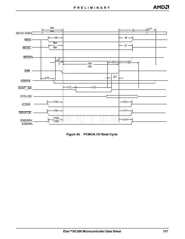
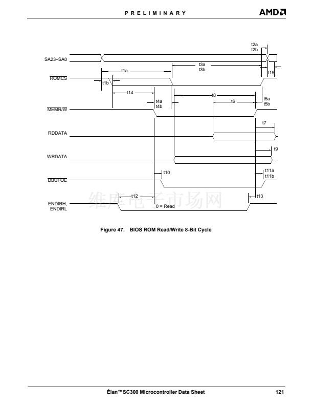
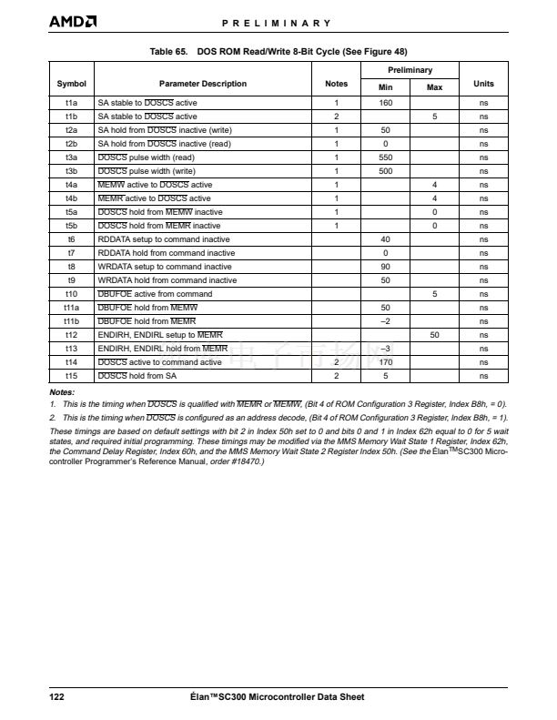
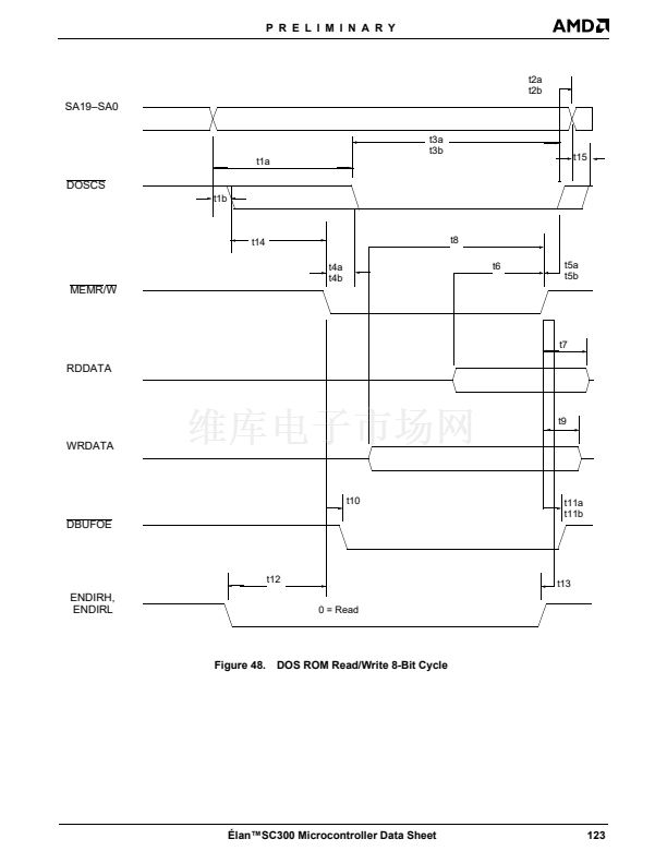
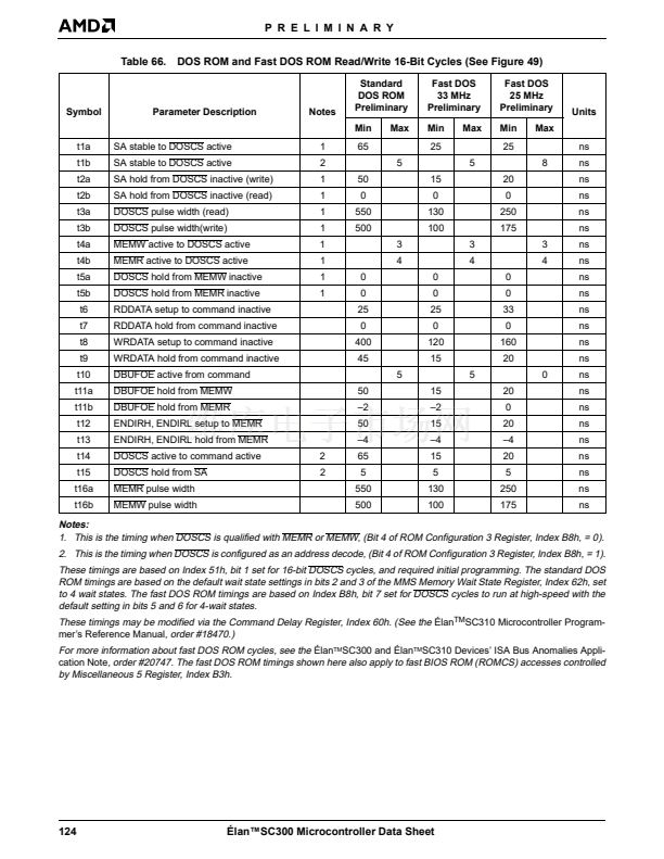
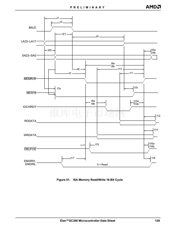
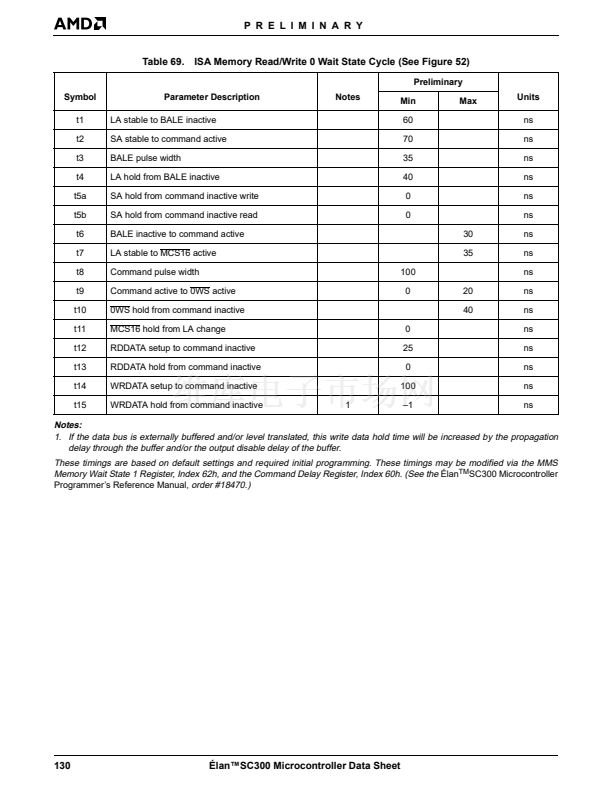
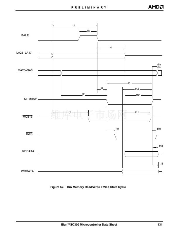
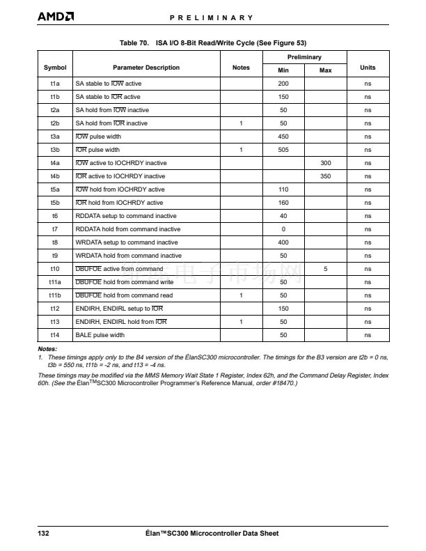
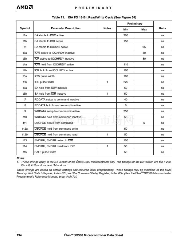
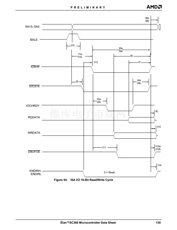
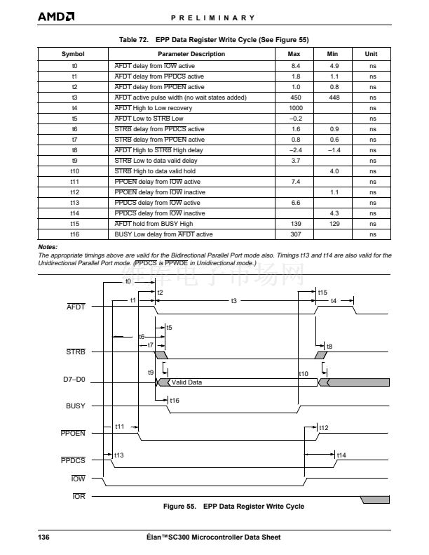
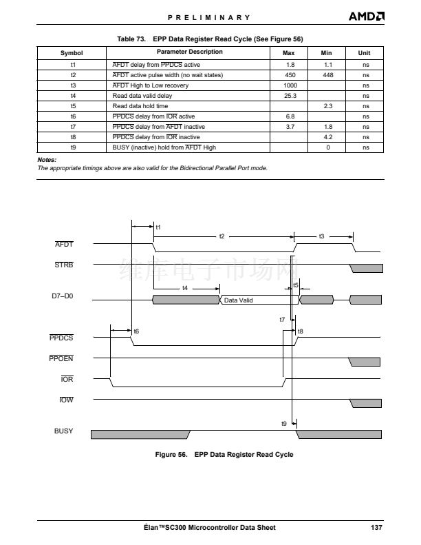
P R E L I M I N A R Y
M
[X14OUT]
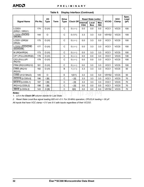
LCD Panel AC Modulation (Output)
In internal LCD mode, this is the AC modulation signal
for the LCD. AC modulation causes the LCD to change
polarity on its crystal material to keep the LCD from
forming a DC bias. Some LCD panels do not require
this signal. Connect M to the equivalent line on the LCD
panel if appropriate.
LCD Physical Pin Connections
To connect an LCD panel to the 脡lanSC300 microcon-
troller, the following pins need to be connected:
n
CP1
n
CP2
n
FRM
n
LCDD3鈥揕CDD0
n
LCDDL3鈥揕CDDL0 (dual-scan panel only)
n
M
The other connections that are required vary. For ex-
ample:
n
Contrast voltage can be positive or negative, typi-
cally about -22 V.
n
+5 V
n
GND
n
Display enable usually requires a simple 5-V enable
signal that some panels require. This can easily be
connected to one of the 脡lanSC300 microcontrol-
ler鈥檚 PMC pins.
n
V
EE
is typically a voltage in the same range as the
contrast voltage. Refer to the panel specifications
for more information.
14-MHz Output
The Parallel Port AFDT output can be programmed to
become X14OUT, a 14.336-MHz clock.
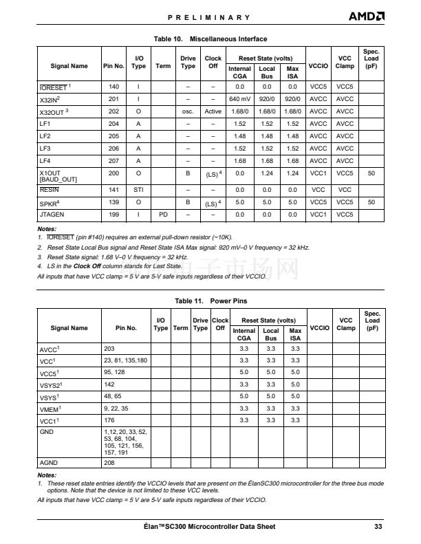
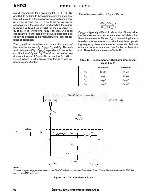
X32IN, X32OUT
32.768-kHz Crystal Interface
These pins are used for the 32.768-kHz crystal. This is
the main clock source for the 脡lanSC300 microcontrol-
ler and is used to drive the internal Phase-Locked
Loops that generate all other clock frequencies needed
in the system. For more information, see 鈥淐rystal Spec-
ifications鈥?on page 95.
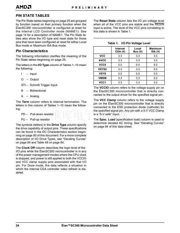
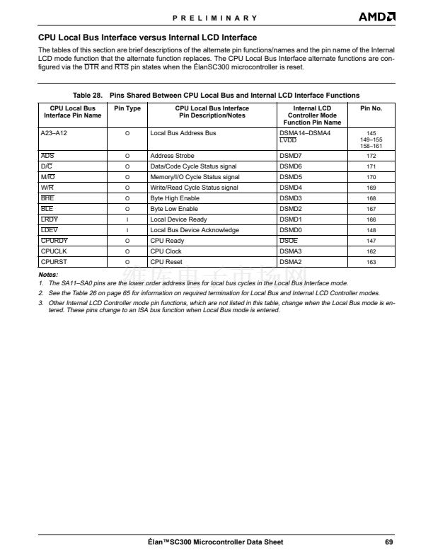
LOCAL BUS INTERFACE
The local bus interface pins are only available when the
脡lanSC300 microcontroller鈥檚 internal LCD controller is
disabled and the 脡lanSC300 microcontroller pin config-
uration is set to support a CPU local bus and a partial
ISA bus.
The following list of pins is specific to local bus function-
ality. In Local Bus mode, additional ISA pins are also
available. These pins are described in the next section
鈥淢aximum ISA Bus Interface鈥?because these pins are
available in both Local Bus and Maximum ISA Bus
modes. For more information, see 鈥淐PU Local Bus In-
terface versus Internal LCD Interface鈥?on page 69 and
Tables 37鈥?on page 73.
A23鈥揂12
Local Bus Upper Address Lines (Output)
These signals are the local bus CPU address lines
when in Local Bus mode. These signals are combined
with the SA11鈥揝A0 signals to form the complete CPU
address bus during local bus cycles.
ADS
MISCELLANEOUS INTERFACE
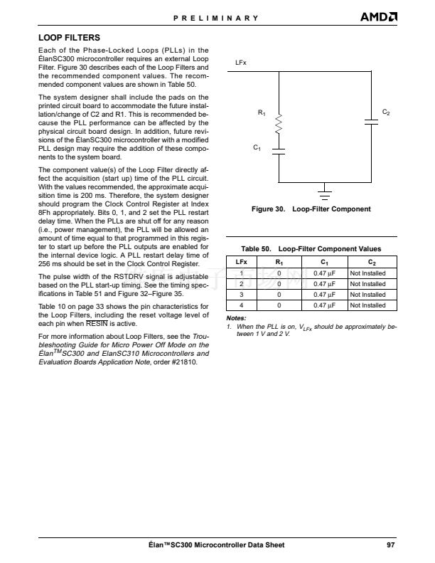
LF1, LF2, LF3, LF4 (Analog inputs)
Local Bus Address Strobe (Output; Active Low)
Local Bus Address Strobe is an active Low address
strobe signal for 386 local bus devices.
BHE
Loop Filters
These pins are used to connect external components
that make up the loop filters for the internal PLLs. For
more information, see 鈥淟oop Filters鈥?on page 97.
X1OUT [BAUD_OUT]
Local Bus Byte High Enable (Output; Active Low)
This signal indicates to the local bus devices that data
is being transferred on the high byte of the data bus.
BLE
14-MHz/UART Output
This can be programmed to be either the 14.336-MHz
clock or the serial baud rate clock for serial infrared de-
vices. The 14.336-MHz output can be used by external
video controllers. As BAUD_OUT, it is 16 x the bit data
rate of the serial port and is used by serial infrared de-
vices.
Local Bus Byte Low Enable (Output; Active Low)
This signal indicates to the local bus devices that data
is being transferred on the low byte of the data bus.
42
脡lan鈩C300 Microcontroller Data Sheet


 1
1
 2
2
 3
3
 4
4
 5
5
 6
6
 7
7
 8
8
 9
9
 10
10
 11
11
 12
12
 13
13
 14
14
 15
15
 16
16
 17
17
 18
18
 19
19
 20
20
 21
21
 22
22
 23
23
 24
24
 25
25
 26
26
 27
27
 28
28
 29
29
 30
30
 31
31
 32
32
 33
33
 34
34
 35
35
 36
36
 37
37
 38
38
 39
39
 40
40
 41
41
 42
42
 43
43
 44
44
 45
45
 46
46
 47
47
 48
48
 49
49
 50
50
 51
51
 52
52
 53
53
 54
54
 55
55
 56
56
 57
57
 58
58
 59
59
 60
60
 61
61
 62
62
 63
63
 64
64
 65
65
 66
66
 67
67
 68
68
 69
69
 70
70
 71
71
 72
72
 73
73
 74
74
 75
75
 76
76
 77
77
 78
78
 79
79
 80
80
 81
81
 82
82
 83
83
 84
84
 85
85
 86
86
 87
87
 88
88
 89
89
 90
90
 91
91
 92
92
 93
93
 94
94
 95
95
 96
96
 97
97
 98
98
 99
99
 100
100
 101
101
 102
102
 103
103
 104
104
 105
105
 106
106
 107
107
 108
108
 109
109
 110
110
 111
111
 112
112
 113
113
 114
114
 115
115
 116
116
 117
117
 118
118
 119
119
 120
120
 121
121
 122
122
 123
123
 124
124
 125
125
 126
126
 127
127
 128
128
 129
129
 130
130
 131
131
 132
132
 133
133
 134
134
 135
135
 136
136
 137
137
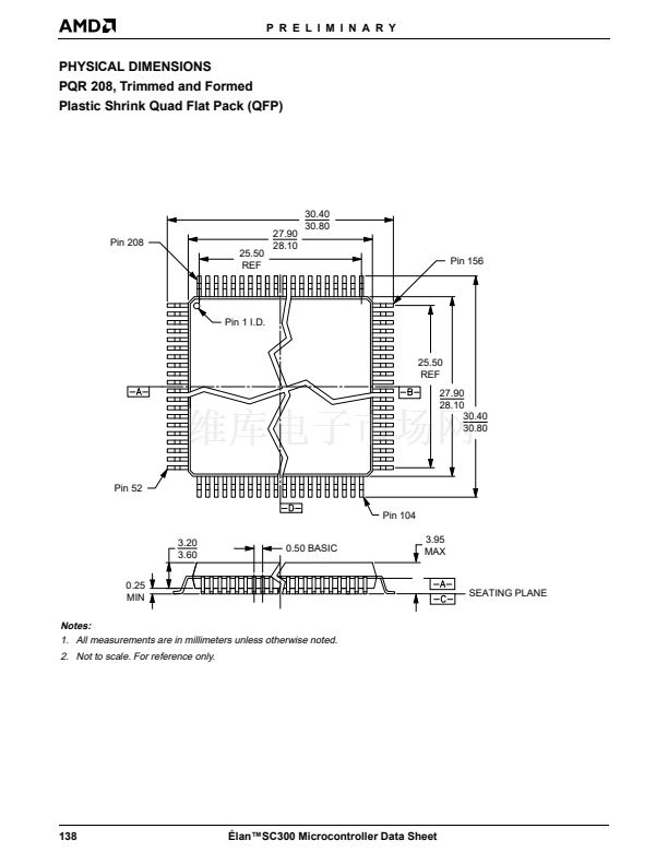 138
138
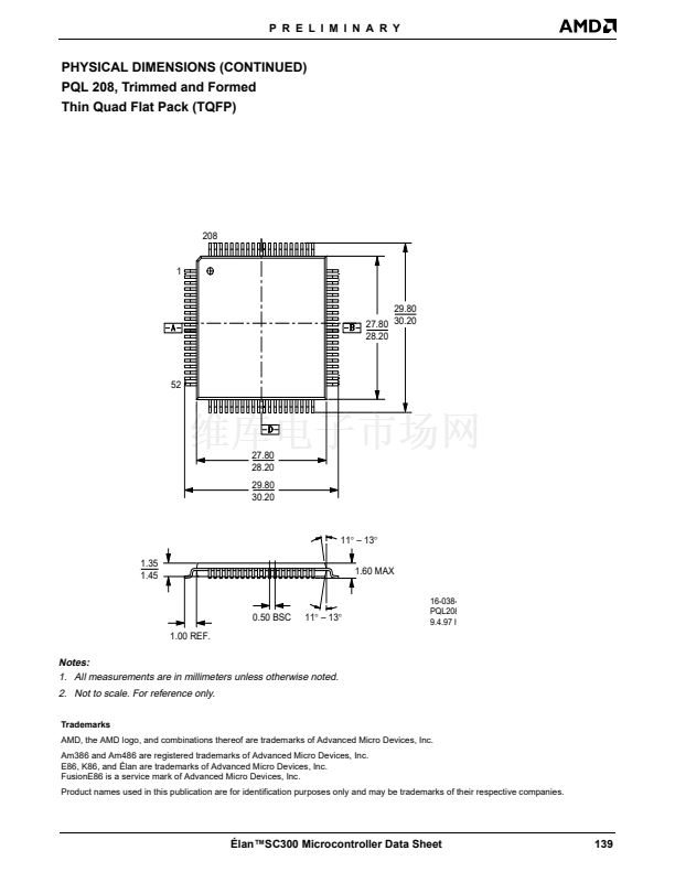 139
139
