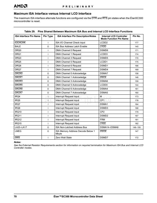
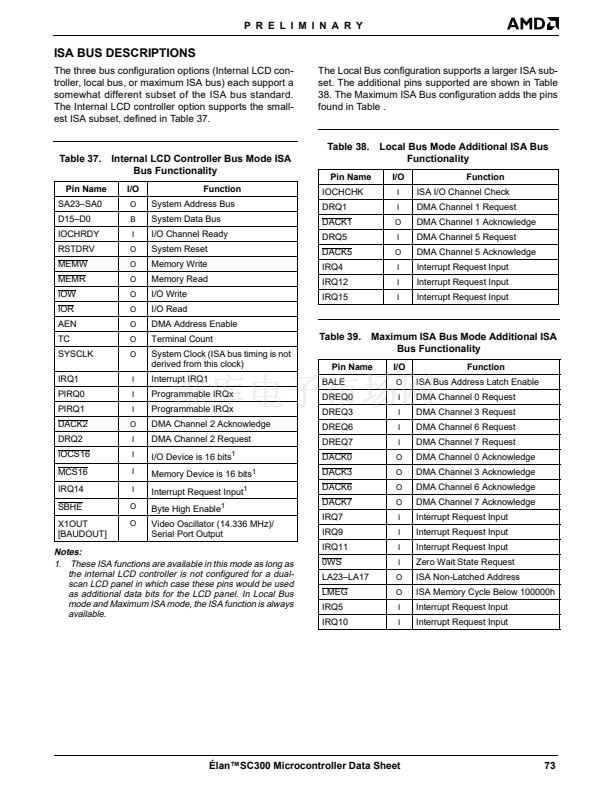
The pins listed below as part of the 鈥淚SA Bus Interface鈥?/div>
are only available when the 脡lanSC300 microcontroller
pin configuration is configured to enable the maximum
ISA Bus. When the maximum ISA bus interface is en-
abled, the internal LCD controller and the CPU local
bus interface are disabled. (This mode does not sup-
port master and ISA refresh cycles.)
For more information, see 鈥淢aximum ISA Interface ver-
sus Internal LCD Interface鈥?on page 70, Table 37鈥揟able
on page 73, and the
脡lan
TM
SC300 and 脡lan
TM
SC310
Devices鈥?ISA Bus Anomalies Application Note
, order
#20747.
0WS
CPU 2X Clock (Output)
This is the timing reference for the local bus device.
The high-speed PLL can be programmed to provide
one of the clock frequencies shown on page 53.
CPURDY
386 CPU Ready Signal (Output; Active Low)
This signal shows the current state of the 386 core
CPU鈥檚 CPURDY signal.
CPURST
CPU Reset (Output; Active High)
This signal is used to force the local bus device to an
initial condition. It is also used to allow the local bus de-
vice to synchronize to the CPUCLK. This signal is
taken directly from the internal CPU reset.
D/C
Local Bus Data/Control (Output; Active Low)
This signal indicates to the local bus devices that the
current cycle is either a Data cycle or a Control cycle.
A Low on this signal indicates that the current cycle is
a Control cycle.
LDEV
Zero Wait State (Input; Active Low)
This input can be driven active by an ISA memory de-
vice to indicate that it can accept a Zero Wait State
memory cycle.
BALE
Bus Address Latch Enable (Output; Active High)
This PC/AT-compatible signal is used by external de-
vices to latch the LA signals for the current cycle.
DACK7, DACK6, DACK5, DACK3, DACK2, DACK1,
DACK0
Local Bus Device Select (Input; Active Low)
This signal is used by the local bus devices to signal
that they will respond to the current cycle. If LDEV is
not driven active by the time specified in Table 57 on
page 108, then the cycle defaults to an ISA bus cycle.
LRDY
DMA Acknowledge (Output; Active Low)
DMA acknowledge signals are active Low output pins
that acknowledge their corresponding DMA requests.
Note:
The DACK2 signal is available regardless of the
脡lanSC300 microcontroller鈥檚 bus mode. DACK1 and
DACK5 are also available in the local bus pin configu-
ration.
DRQ7, DRQ6, DRQ5, DRQ3, DRQ2, DRQ1, DRQ0
Local Bus Device Ready (Input; Active Low)
This signal is used by the local bus devices to terminate
the current bus cycle.
M/IO
DMA Request (Input; Active High)
DMA Request signals are asynchronous DMA channel
request inputs used by peripheral devices to gain ac-
cess to a DMA service.
Local Bus Memory/I/O (Output; Active Low)
This signal indicates to the local bus devices that the
current cycle is either a memory or an I/O cycle. A Low
on this signal indicates that the current cycle is an I/O
cycle.
W/R
Note:
The DRQ2 signal is available regardless of the
脡lanSC300 microcontroller鈥檚 bus mode. DRQ1 and
DRQ5 are also available in the local bus pin configura-
tion.
IOCHCHK
Local Bus Write/Read (Output; Active Low)
This signal indicates to the local bus devices that the
current cycle is either a Read or a Write cycle. A Low
on this signal indicates that the current cycle is a Read
cycle.
I/O Channel Check (Input; Active Low)
This is a PC/AT-compatible signal used to generate an
NMI or SMI.
Note:
IOCHCHK is also available in the Local Bus pin
configuration.
脡lan鈩C300 Microcontroller Data Sheet
43


 1
1
 2
2
 3
3
 4
4
 5
5
 6
6
 7
7
 8
8
 9
9
 10
10
 11
11
 12
12
 13
13
 14
14
 15
15
 16
16
 17
17
 18
18
 19
19
 20
20
 21
21
 22
22
 23
23
 24
24
 25
25
 26
26
 27
27
 28
28
 29
29
 30
30
 31
31
 32
32
 33
33
 34
34
 35
35
 36
36
 37
37
 38
38
 39
39
 40
40
 41
41
 42
42
 43
43
 44
44
 45
45
 46
46
 47
47
 48
48
 49
49
 50
50
 51
51
 52
52
 53
53
 54
54
 55
55
 56
56
 57
57
 58
58
 59
59
 60
60
 61
61
 62
62
 63
63
 64
64
 65
65
 66
66
 67
67
 68
68
 69
69
 70
70
 71
71
 72
72
 73
73
 74
74
 75
75
 76
76
 77
77
 78
78
 79
79
 80
80
 81
81
 82
82
 83
83
 84
84
 85
85
 86
86
 87
87
 88
88
 89
89
 90
90
 91
91
 92
92
 93
93
 94
94
 95
95
 96
96
 97
97
 98
98
 99
99
 100
100
 101
101
 102
102
 103
103
 104
104
 105
105
 106
106
 107
107
 108
108
 109
109
 110
110
 111
111
 112
112
 113
113
 114
114
 115
115
 116
116
 117
117
 118
118
 119
119
 120
120
 121
121
 122
122
 123
123
 124
124
 125
125
 126
126
 127
127
 128
128
 129
129
 130
130
 131
131
 132
132
 133
133
 134
134
 135
135
 136
136
 137
137
 138
138
 139
139
