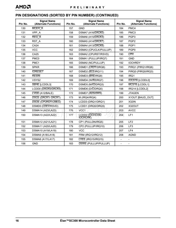
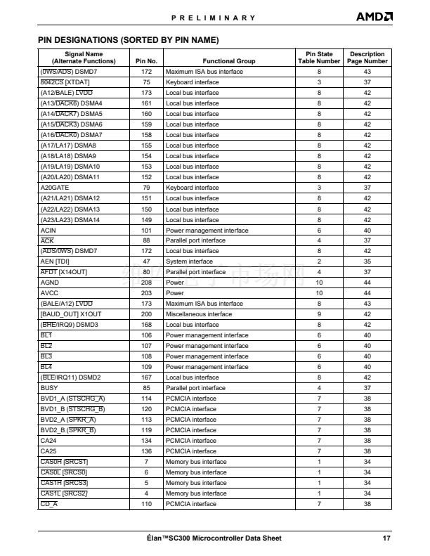
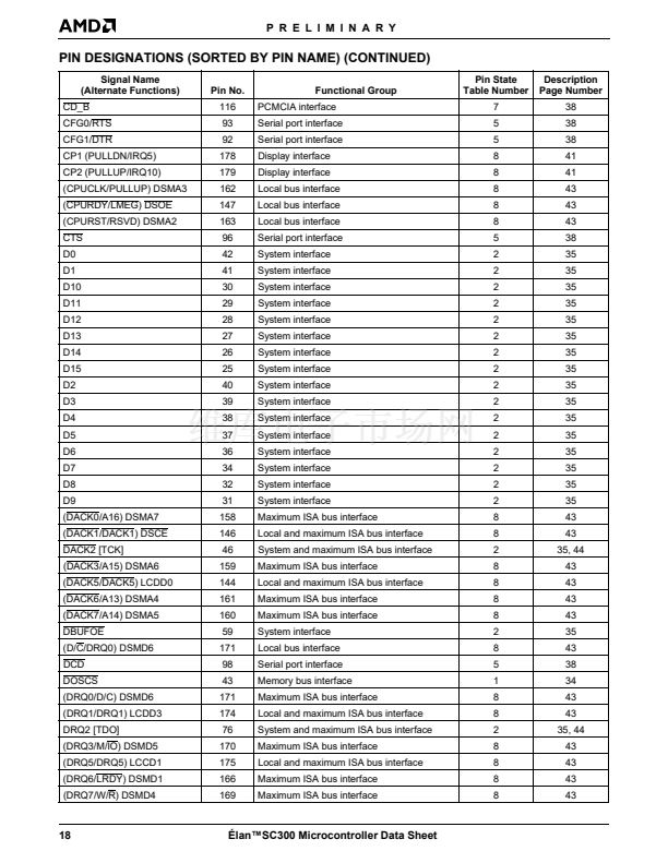
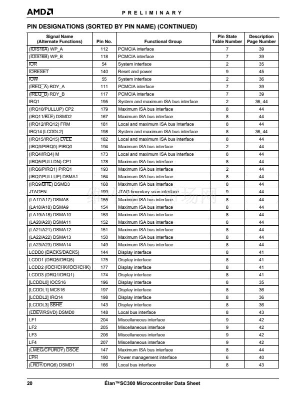
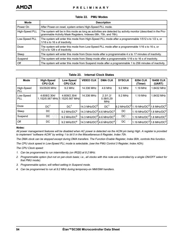
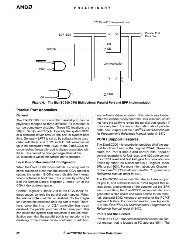
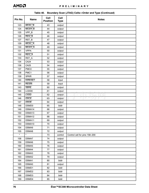
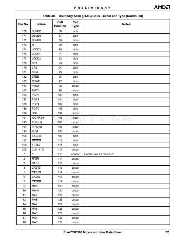
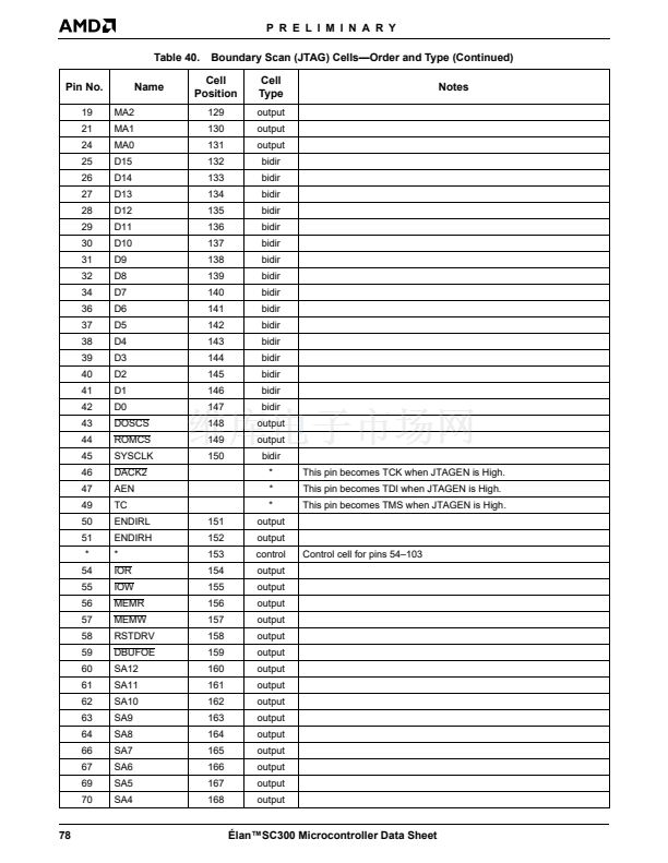
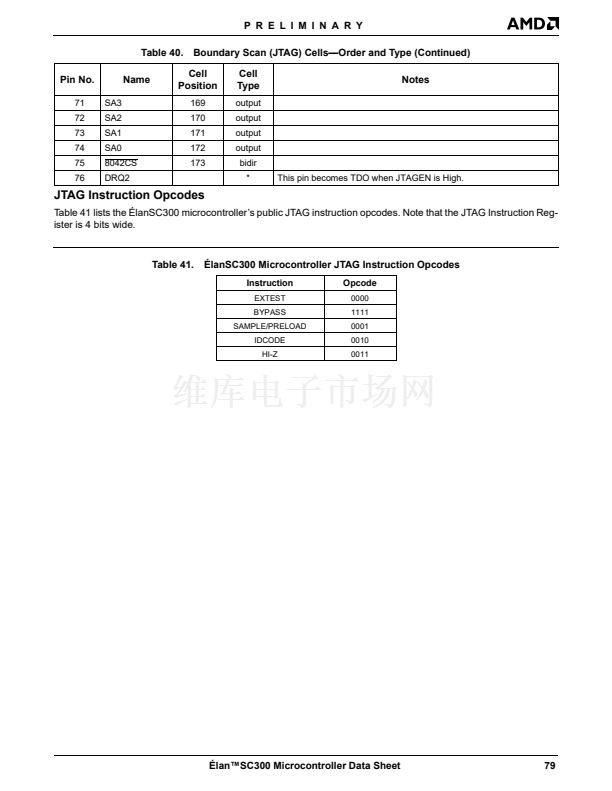
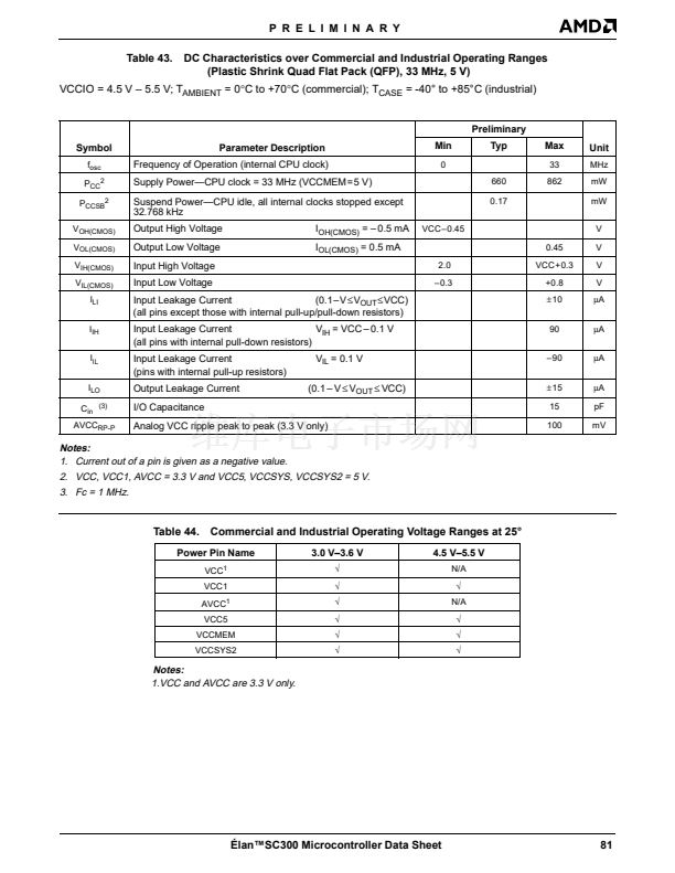
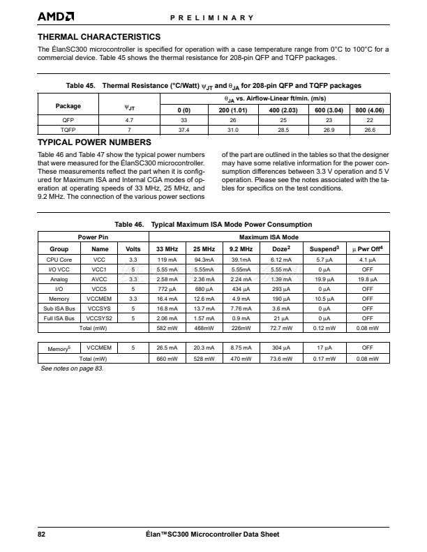
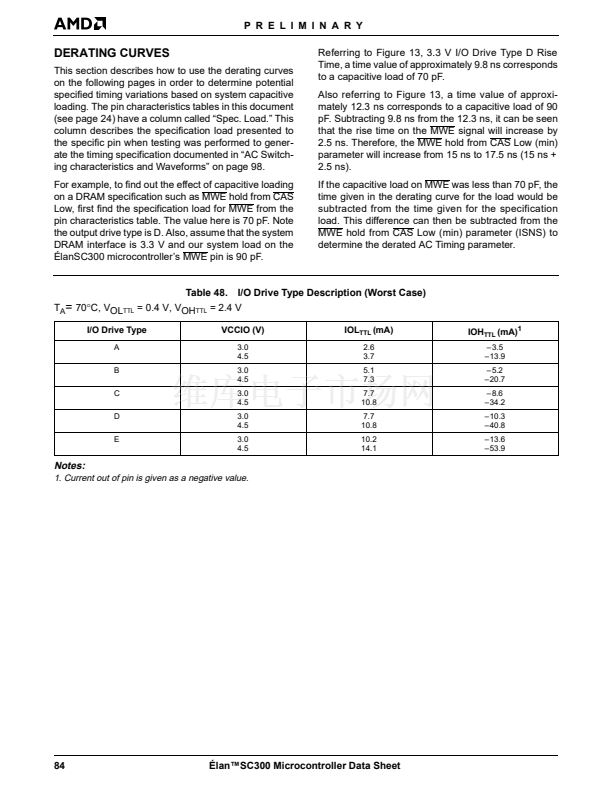
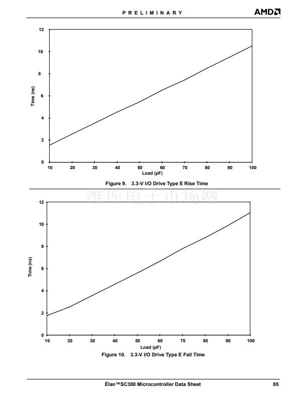
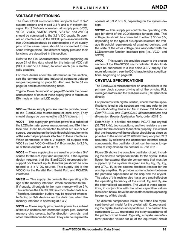
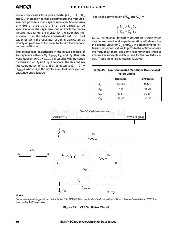
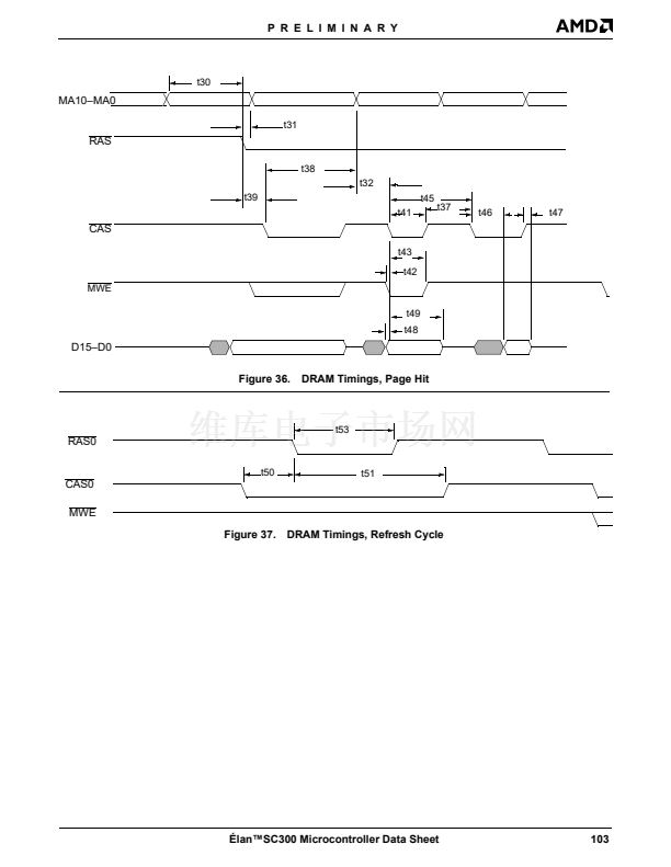
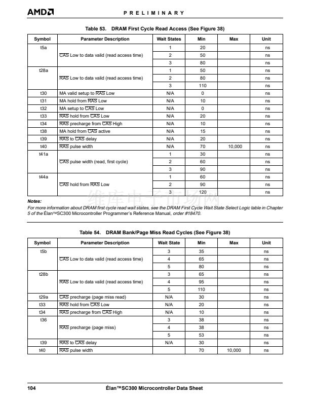
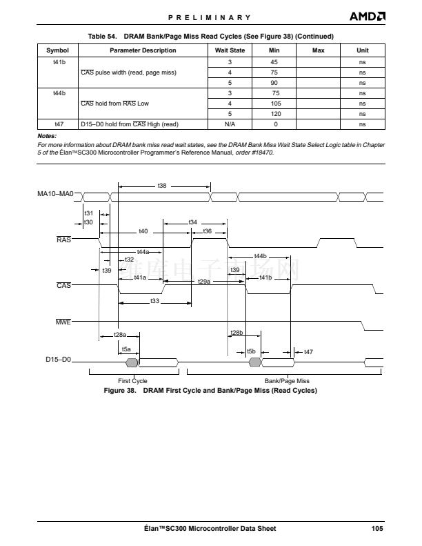
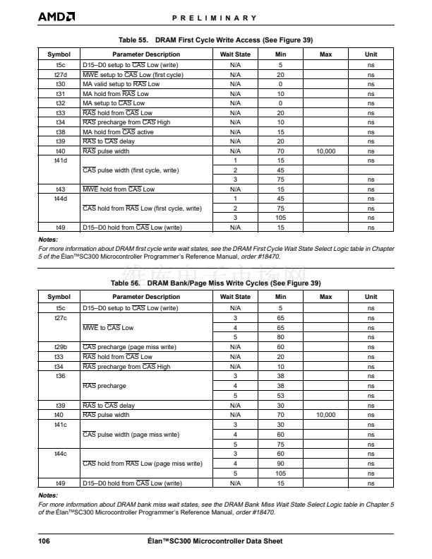
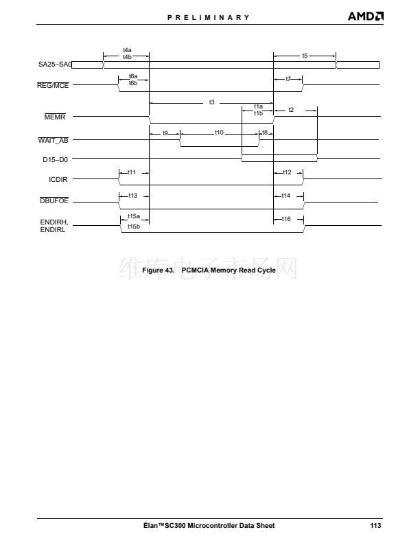
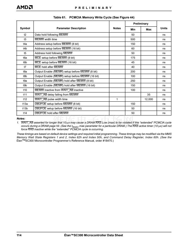
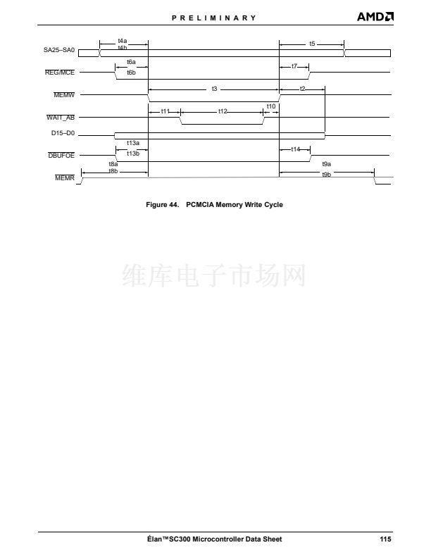
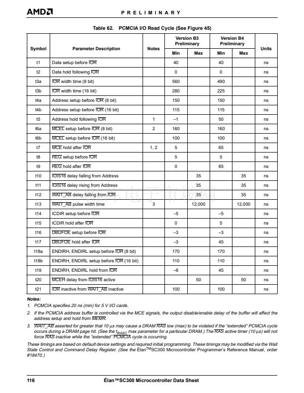
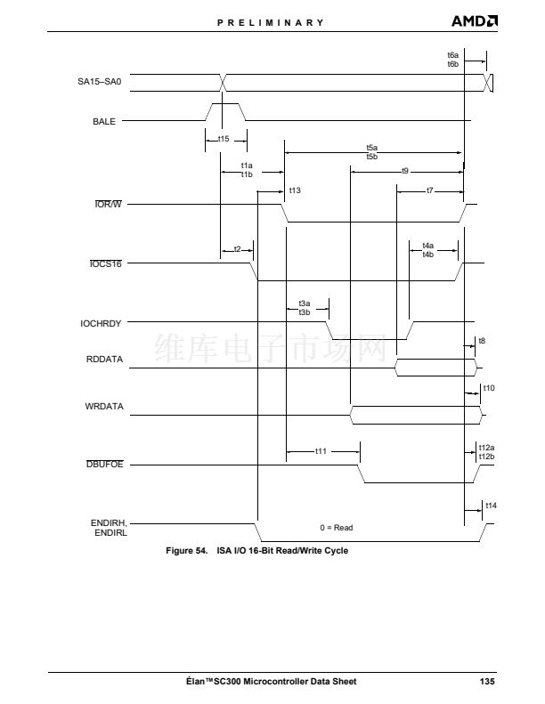
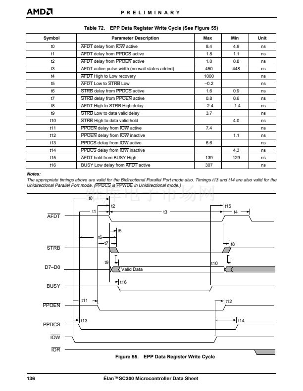
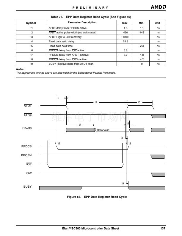
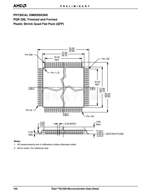
P R E L I M I N A R Y
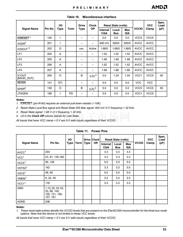
AVCC is required for battery backup. For more informa-
tion about battery backup, see the
脡lan
TM
SC300 and
脡lan
TM
SC310 Microcontrollers Solution For Systems
Using a Back-Up Battery Application Note
, order
#20746.
GND
VMEM
3.3-V or 5-V Supply Pins
These supply pins provide power to the Memory Inter-
face and Data Bus pins (D15鈥揇0). These pins must be
connected to the same DC supply as the system
DRAMs.
VSYS
System Ground Pins
These pins provide electric grounding to all non-analog
sections of the 脡lanSC300 microcontroller鈥檚 internal
CPU and peripherals.
IORESET
3.3 V or 5 V Supply Pins
These supply pins provide power to a subset of the ISA
address and command signal pins, in addition to exter-
nal memory chip selects, buffer direction controls, and
other miscellaneous functions.
VSYS2
Reset Input (Input; Active Low)
IORESET is an asynchronous hardware reset input
equivalent to POWERGOOD in the PC/AT system ar-
chitecture. Asserting this signal does not reset the RTC
RAM invalid bit.
Asserting IORESET without asserting RESIN causes
the 脡lanSC300 microcontroller to go into Micro Power
Off mode. For more information, see 鈥淢icro Power Off
Mode鈥?on page 55.
RESIN
3.3 V or 5 V Supply Pins
These supply pins provide power to some of the
脡lanSC300 microcontroller alternate system interface
pins.
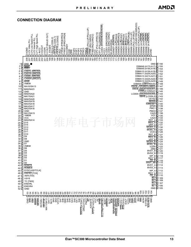
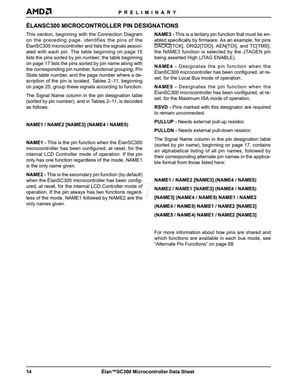
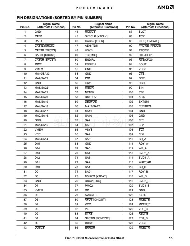
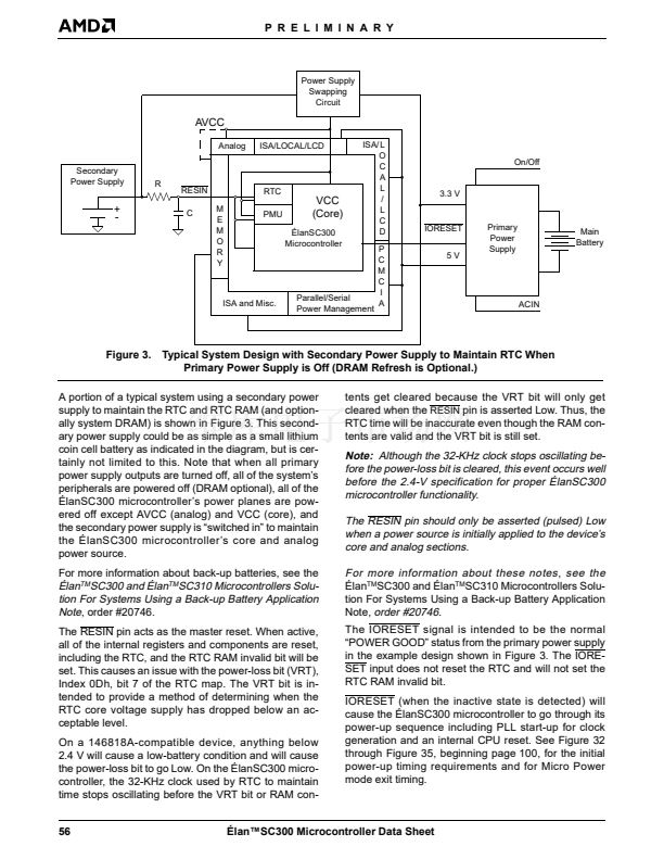
FUNCTIONAL DESCRIPTION
The 脡lanSC300 microcontroller architecture consists
of several components, as shown in the device block
diagram. These components can be grouped into eight
main functional modules:
1. The Am386SXLV microprocessor core itself, includ-
ing System Management Mode (SMM) power man-
agement hardware
2. A memory controller and associated mapping hard-
ware
3. Two PCMCIA Revision 2.1 slots
4. An additional power management controller that in-
terfaces to the CPU鈥檚 System Management Mode
(SMM) and is integrated tightly with internal clock
generator hardware
5. Core peripheral controllers (DMA, interrupt control-
ler, and timer)
6. Additional peripheral controllers (UART, parallel
port, and real-time clock)
7. PC/AT support features
8. An integrated LCD controller, optional local bus
controller, or optional maximum ISA bus
The remainder of this section describes these mod-
ules.
Master Reset (Input; Active Low)
RESIN indicates that main power is being applied to
the 脡lanSC300 microcontroller for the first time. When
this signal is asserted, the RTC and internal registers
are reset.
The RESIN signal supersedes the
IORESET
signal.
VCC
3.3 V (only) DC Supply Pins
These supply pins provide power to the 脡lanSC300 mi-
crocontroller core. Refer to AC Characteristics for VCC
power up timing restrictions.
The VCC pins are required for battery backup. For
more information about battery backup, see the
脡lan
TM
SC300 and 脡lan
TM
SC310 Microcontrollers Solu-
tion For Systems Using a Back-Up Battery Application
Note
, order #20746.
VCC1
3.3 V or 5 V Supply Pin
This supply pin provides power to a subset of the LCD/
alternate, power management, and ISA interface pins.
VCC5
5 V DC Supply Pins
These supply pins provide power to the 5 V only inter-
face pins. These pins could be 3.3 V in a pure 3.3-V
system.
Am386SXLV CPU Core
The CPU core component is a full implementation of
the AMD Am386SXLV 32-bit, low-voltage microproces-
sor (with I/O pads removed). For more information
about the Am386 microprocessors, see the
脡lan鈩C300 Microcontroller Data Sheet
45


 1
1
 2
2
 3
3
 4
4
 5
5
 6
6
 7
7
 8
8
 9
9
 10
10
 11
11
 12
12
 13
13
 14
14
 15
15
 16
16
 17
17
 18
18
 19
19
 20
20
 21
21
 22
22
 23
23
 24
24
 25
25
 26
26
 27
27
 28
28
 29
29
 30
30
 31
31
 32
32
 33
33
 34
34
 35
35
 36
36
 37
37
 38
38
 39
39
 40
40
 41
41
 42
42
 43
43
 44
44
 45
45
 46
46
 47
47
 48
48
 49
49
 50
50
 51
51
 52
52
 53
53
 54
54
 55
55
 56
56
 57
57
 58
58
 59
59
 60
60
 61
61
 62
62
 63
63
 64
64
 65
65
 66
66
 67
67
 68
68
 69
69
 70
70
 71
71
 72
72
 73
73
 74
74
 75
75
 76
76
 77
77
 78
78
 79
79
 80
80
 81
81
 82
82
 83
83
 84
84
 85
85
 86
86
 87
87
 88
88
 89
89
 90
90
 91
91
 92
92
 93
93
 94
94
 95
95
 96
96
 97
97
 98
98
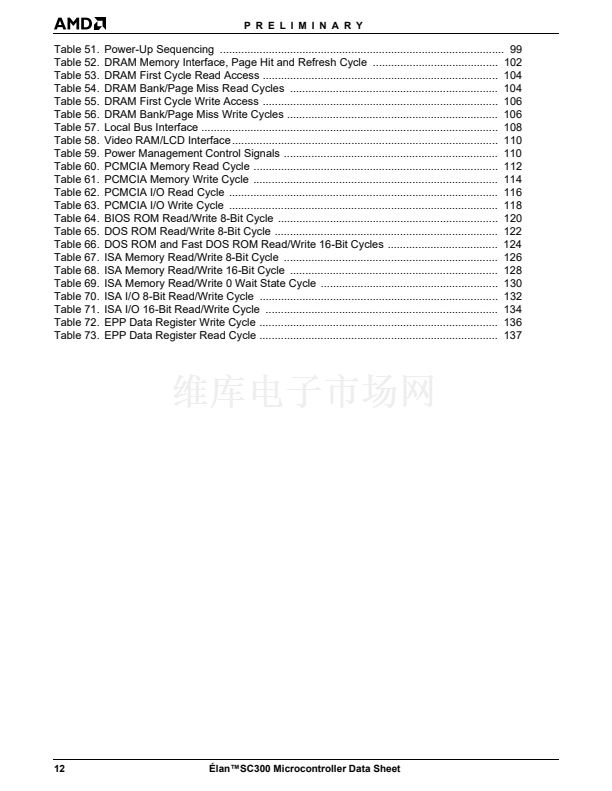
 99
99
 100
100
 101
101
 102
102
 103
103
 104
104
 105
105
 106
106
 107
107
 108
108
 109
109
 110
110
 111
111
 112
112
 113
113
 114
114
 115
115
 116
116
 117
117
 118
118
 119
119
 120
120
 121
121
 122
122
 123
123
 124
124
 125
125
 126
126
 127
127
 128
128
 129
129
 130
130
 131
131
 132
132
 133
133
 134
134
 135
135
 136
136
 137
137
 138
138
 139
139
