P R E L I M I N A R Y
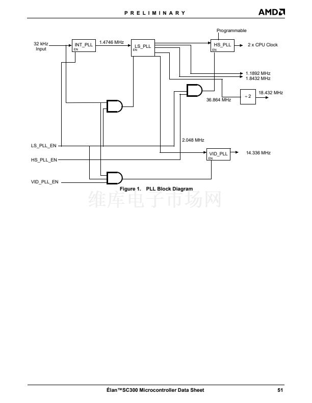
In the PLL Block Diagram, the INT_PLL is the Interme-
diate PLL, and is used to multiply the 32.768-kHz input
frequency by 45 to produce a 1.4746-MHz input for use
by the LS_PLL and the VID_PLL. The LS_PLL, or Low-
Speed PLL, is used to again multiply the 1.4746-MHz
input by 25 to produce a 36.864-MHz output. This out-
put of the LS_PLL is then divided down to provide the
frequencies shown in Table 21.
The LS_PLL also generates a 2.048-MHz signal used
by the VID_PLL or Video PLL to generate the
14.336-MHz clock used by the Internal LCD Controller.
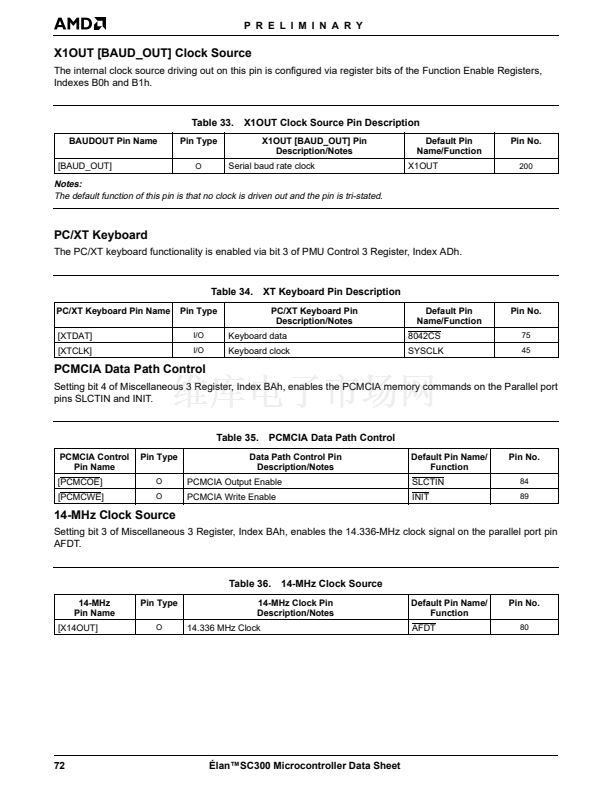
This frequency is also available on the X1OUT pin for
use by an external video controller if selected.
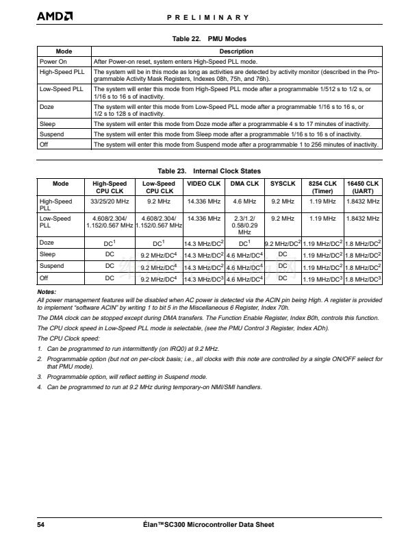
The HS_PLL can be programmed to provide one of the
high-speed CPU clock frequencies shown in Table 20.
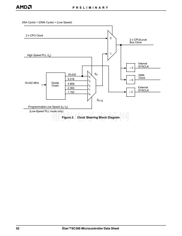
During operation in Low-Speed PLL mode, the CPU
clock is driven from Low-Speed clock output of the
Low-Speed PLL divide chain. The CPU clock fre-
quency used during Low Speed mode is programma-
ble to the following frequencies: 4.608 MHz, 2.304
MHz, 1.152 MHz, and 0.567 MHz. During Doze, Sleep,
and Suspend modes of operation, the CPU clock is
normally stopped. This clock operates at 9.216 MHz
when it is running.
Slow-refresh and self-refresh DRAMs are supported by
the 脡lanSC300 microcontroller. The refresh timer
source and the refresh rate are selectable. When the
CPU clock is stopped, the only clock source for refresh
is the 32-kHz clock. CAS-before-RAS DRAM refresh is
performed.
When the DMA subsystem is idle, the DMA clock con-
trol logic stops the clock input to the DMA controllers.
The DMA clock is started whenever any of the DREQ
inputs go High. When the DMA cycle is in progress, the
DMA clock remains active as long as a DREQ input is
High or the internal AEN signal is active.
To reduce power consumption in Doze, Sleep, and
Suspend modes, the CPU clock is turned off. To further
reduce the power consumption in these three modes,
the High-Speed PLL is shut off. The Low-Speed PLL is
left on by default, but can be programmed to turn off in
all three modes.
For information about the signals associated with
power management (ACIN, BL4鈥揃L1, EXTSMI, LPH,
PGP3鈥揚GP0, PMC4鈥揚MC0, and SUS/RES), see
鈥淧ower Management Interface鈥?on page 40. For more
information, see Chapter 1 of the
脡lan
TM
SC300 Micro-
controller Programmer鈥檚 Reference Manual
, order
#18470.
Table 20.
High-Speed CPU Clock Frequencies
HS_PLL Output Frequency
39.496 MHz
50.023 MHz
65.829 MHz
2 x CPU Frequency
40 MHz
50 MHz
66 MHz
脡lanSC300 Microcontroller
Power Management
Dynamic CPU clock switching is the primary form of
power management in the 脡lanSC300 microcontroller.
When the system is in the High-Speed PLL mode, the
脡lanSC300 microcontroller can be configured to use
the High-Speed clock output of the PLL for main mem-
ory, local bus accesses, CPU idle cycles, and ROM ac-
cesses configured to use the High-Speed clock. During
cycles to I/O devices, PCMCIA, ROM, and other exter-
nal ISA devices, the CPU clock is dynamically switched
to the output of the Low-Speed PLL.
Table 21.
Phase-Locked Loops
INT_PLL
LS_PLL
Frequency
1.4746 MHz
36.864 MHz
1.8432 MHz
1.1892 MHz
HS_PLL
VID_PLL
39.496 MHz, 50.023 MHz,
or 65.829 MHz
14.336 MHz
PLL Output
Where Used
LS_PLL and VID_PLL
Divide by 2
16450 UART clock
8254 Timer clock
Input to high speed/low speed MUX
LCD Controller
脡lan鈩C300 Microcontroller Data Sheet
53


 1
1
 2
2
 3
3
 4
4
 5
5
 6
6
 7
7
 8
8
 9
9
 10
10
 11
11
 12
12
 13
13
 14
14
 15
15
 16
16
 17
17
 18
18
 19
19
 20
20
 21
21
 22
22
 23
23
 24
24
 25
25
 26
26
 27
27
 28
28
 29
29
 30
30
 31
31
 32
32
 33
33
 34
34
 35
35
 36
36
 37
37
 38
38
 39
39
 40
40
 41
41
 42
42
 43
43
 44
44
 45
45
 46
46
 47
47
 48
48
 49
49
 50
50
 51
51
 52
52
 53
53
 54
54
 55
55
 56
56
 57
57
 58
58
 59
59
 60
60
 61
61
 62
62
 63
63
 64
64
 65
65
 66
66
 67
67
 68
68
 69
69
 70
70
 71
71
 72
72
 73
73
 74
74
 75
75
 76
76
 77
77
 78
78
 79
79
 80
80
 81
81
 82
82
 83
83
 84
84
 85
85
 86
86
 87
87
 88
88
 89
89
 90
90
 91
91
 92
92
 93
93
 94
94
 95
95
 96
96
 97
97
 98
98
 99
99
 100
100
 101
101
 102
102
 103
103
 104
104
 105
105
 106
106
 107
107
 108
108
 109
109
 110
110
 111
111
 112
112
 113
113
 114
114
 115
115
 116
116
 117
117
 118
118
 119
119
 120
120
 121
121
 122
122
 123
123
 124
124
 125
125
 126
126
 127
127
 128
128
 129
129
 130
130
 131
131
 132
132
 133
133
 134
134
 135
135
 136
136
 137
137
 138
138
 139
139
