P R E L I M I N A R Y
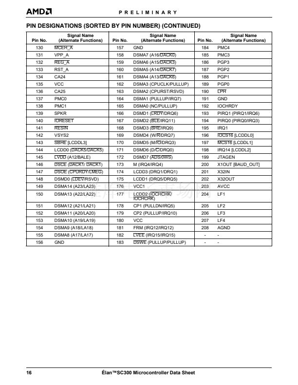
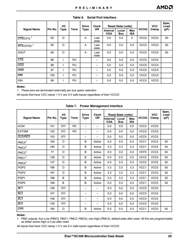
PMC and PGP Pins
The 脡lanSC300 microcontroller supports five power
management control (PMC) pins and four programma-
ble general purpose (PGP) pins. The PMC pins can be
used to control the VCC rails of peripheral devices. The
PMC pins are related to the operating modes of the
脡lanSC300 microcontroller PMU. The PGP pins can be
used as general I/O chip selects for various uses.
The PMC4鈥揚MC0 pins are controlled by Configuration
Registers at Indexes 80h, 81h, ABh, and ACh. Each
pin can be programmed to be activated upon entry into
any of the PMU modes or driven directly by software.
PMC0 can be activated when the system is in High-
Speed PLL or Low-Speed PLL modes; PMC1 when the
system is in Doze mode; PMC2 when the system is in
Sleep mode; PMC3 and PMC4 when the system is in
Suspend mode; or just about any other combination.
These pins can then be used by the system designer to
shut off power to particular peripherals when the sys-
tem enters certain modes, just as internal clocks are
slowed or stopped in these modes. Upon the rising
edge of RESIN, PMC0, PMC1, PMC2, and PMC4 are
asserted Low and PMC3 is asserted High. Prior to this
edge, these signals are undefined.
The 脡lanSC300 microcontroller can be programmed to
reset a timer when an I/O access to a preset address
range is detected. If no I/O activity in that range occurs
before the timer expires, the 脡lanSC300 microcontrol-
ler can assert a PMC signal to turn off the device. When
S/W accesses that address range later, the 脡lanSC300
microprocessor can generate a System Management
Interrupt (SMI) to the processor, which then activates
an SMI handler routine. This routine then can deter-
mine the cause of the SMI and take appropriate action,
such as powering the I/O device back on.
The PGP3鈥揚GP0 pins are controlled by several config-
uration registers (70h, 74h, 89h, 91h, 94h, 95h, 9Ch,
A3h, and A4h) and their behavior is very flexible. PGP0
and PGP1 can be programmed as input or output.
PGP2 and PGP3 are dedicated outputs. PGP1 and
PGP3 can be gated with I/O reads, PGP0 and PGP2
can be gated with I/O writes, or each can act as an ad-
dress decode for a chip select.
The following paragraphs describe the 脡lanSC300 mi-
crocontroller in Micro Power Off mode. The following
are distinctive characteristics:
n
Minimum Power Consumption mode (approxi-
mately 25
碌A
typical, AVCC, and Core VCC com-
bined; AVCC and VCC are mandatory for Micro
Power Off mode).
n
Allows the system designer to utilize the internal
RTC and RTC RAM to maintain time, date, and
system configuration data while the other system
peripherals are powered off.
n
Provides the system designer with the option of
keeping the system DRAM powered and refreshed
while other system peripherals are powered off.
Self-refresh and CAS-before-RAS refresh DRAMs
are supported.
n
Minimal external logic required to properly control
power supplies and/or power switching.
n
No external buffering required to properly power
down system hardware.
The 脡lanSC300 microcontroller allows a system de-
signer to easily maintain the internal RTC and RTC
RAM and optionally, the DRAM interface, while the rest
of the system peripherals attached directly to the de-
vice are powered off. All 脡lanSC300 microcontroller
power pins associated with the I/O pins of external
powered-off peripherals must be powered down also.
This, in addition to internal termination, provides the re-
quired isolation to allow the external peripherals to be
powered off.
Automatically controlled internal I/O termination is pro-
vided to terminate the internal nodes of the 脡lanSC300
microcontroller properly when required.
The DRAM CAS-before-RAS, or self-refresh, can be
maintained by the 脡lanSC300 microcontroller in this
Micro Power State, if configured to do so, utilizing the
32-kHz oscillator. This clock continues to drive the RTC
and a portion of the core logic. See the
脡lan
TM
SC300
and 脡lan
TM
SC310 Microcontrollers Solution For Sys-
tems Using a Back-up Battery Application Note
, order
#20746 for more information about the 32-kHz oscilla-
tor and the RTC. The VMEM power plane (DRAM/
SRAM section power) must remain powered on if the
CAS-before-RAS refresh option is selected while in the
Micro Power state. The VMEM power plane must also
remain powered on if the self-refresh option is selected
and the specific DRAM device requires any of its con-
trol pins (i.e., WE, CAS, RAS, etc.) to remain inactive in
the Self-Refresh mode. If this is not required, it may be
possible for the system designer to remove power from
the VMEM pins when entering the Micro Power state,
even when the Self-Refresh mode DRAMs remain
powered on.
Micro Power Off Mode
Micro Power Off mode is the power management mode
that is used for battery backup.
Micro Power Off mode allows the system designer to
remove power from the VCC1, VSYS, VSYS2, VCC5,
and optionally, VMEM power inputs to the microcontrol-
ler. This allows the RTC timer and RAM contents to be
kept valid by using a battery back-up power source on
the VCC core and AVCC pins, which typically should
use only 25
碌A
in this mode.
脡lan鈩C300 Microcontroller Data Sheet
55


 1
1
 2
2
 3
3
 4
4
 5
5
 6
6
 7
7
 8
8
 9
9
 10
10
 11
11
 12
12
 13
13
 14
14
 15
15
 16
16
 17
17
 18
18
 19
19
 20
20
 21
21
 22
22
 23
23
 24
24
 25
25
 26
26
 27
27
 28
28
 29
29
 30
30
 31
31
 32
32
 33
33
 34
34
 35
35
 36
36
 37
37
 38
38
 39
39
 40
40
 41
41
 42
42
 43
43
 44
44
 45
45
 46
46
 47
47
 48
48
 49
49
 50
50
 51
51
 52
52
 53
53
 54
54
 55
55
 56
56
 57
57
 58
58
 59
59
 60
60
 61
61
 62
62
 63
63
 64
64
 65
65
 66
66
 67
67
 68
68
 69
69
 70
70
 71
71
 72
72
 73
73
 74
74
 75
75
 76
76
 77
77
 78
78
 79
79
 80
80
 81
81
 82
82
 83
83
 84
84
 85
85
 86
86
 87
87
 88
88
 89
89
 90
90
 91
91
 92
92
 93
93
 94
94
 95
95
 96
96
 97
97
 98
98
 99
99
 100
100
 101
101
 102
102
 103
103
 104
104
 105
105
 106
106
 107
107
 108
108
 109
109
 110
110
 111
111
 112
112
 113
113
 114
114
 115
115
 116
116
 117
117
 118
118
 119
119
 120
120
 121
121
 122
122
 123
123
 124
124
 125
125
 126
126
 127
127
 128
128
 129
129
 130
130
 131
131
 132
132
 133
133
 134
134
 135
135
 136
136
 137
137
 138
138
 139
139
