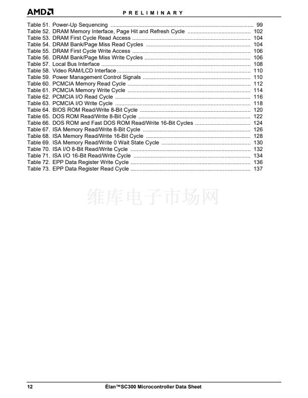
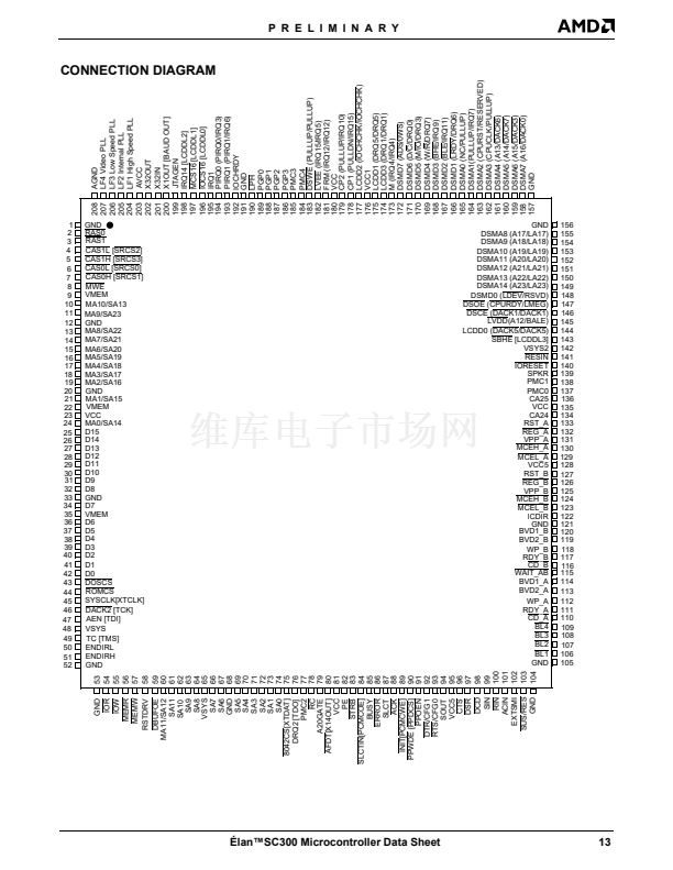
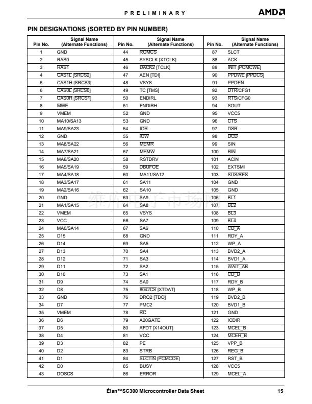
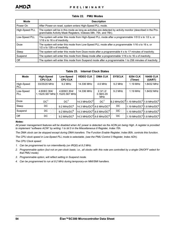
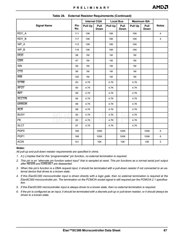
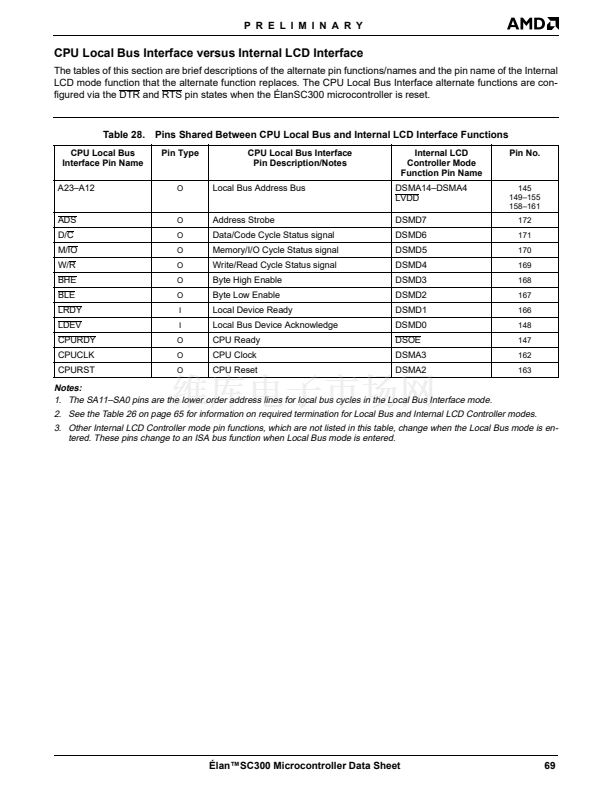
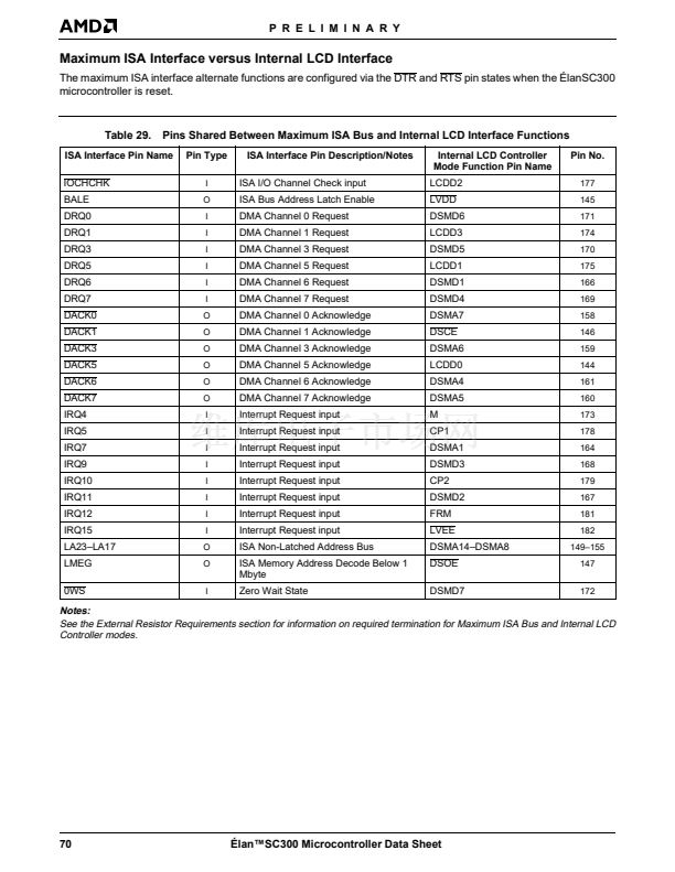
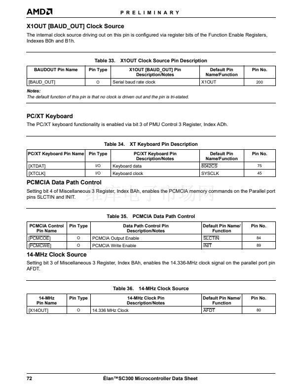
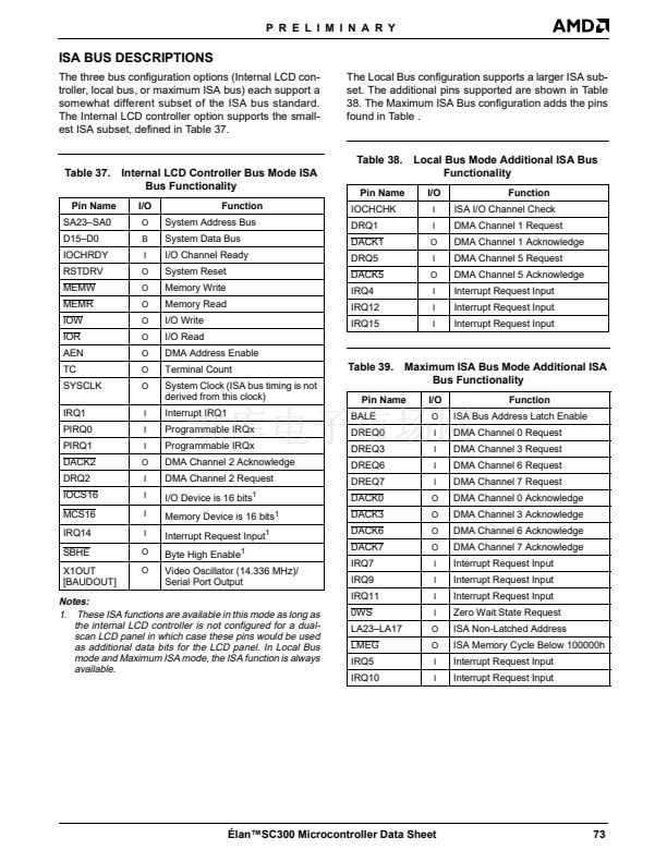
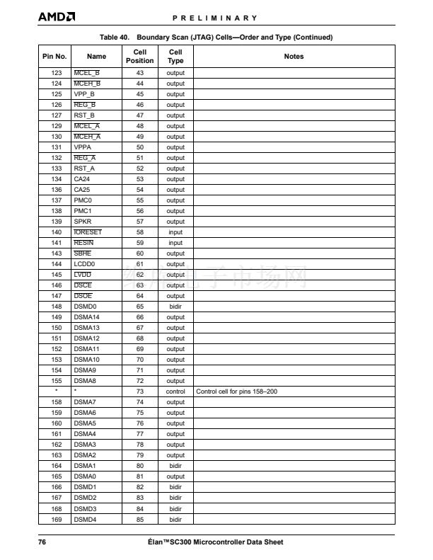
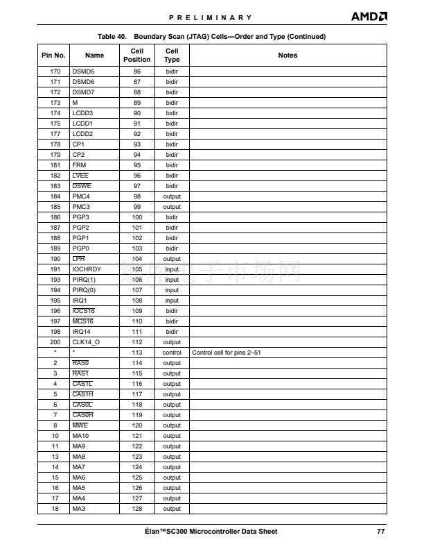
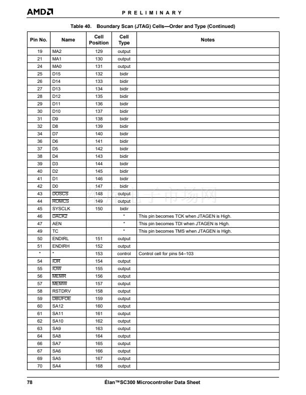
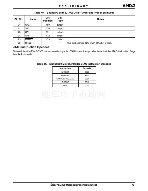
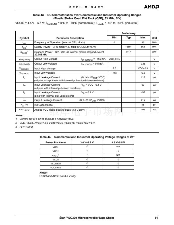
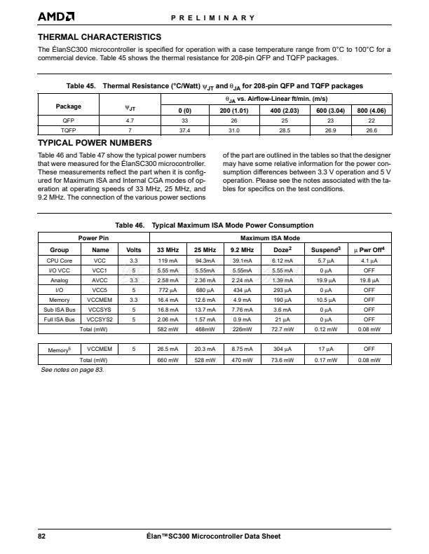
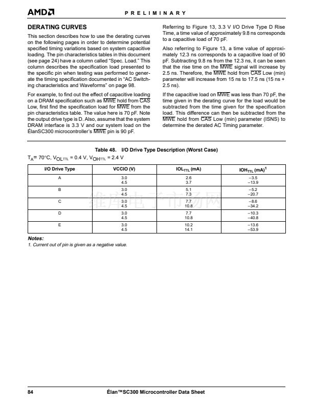
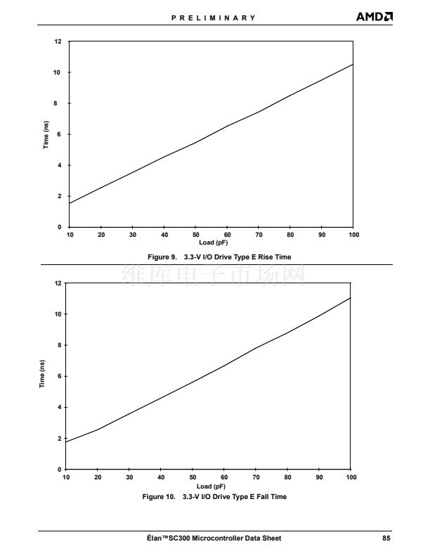
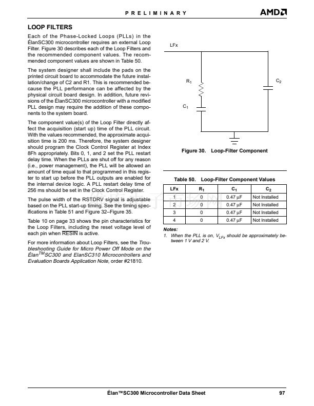
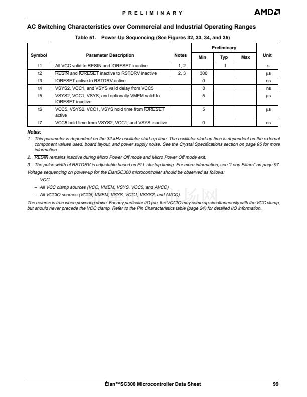
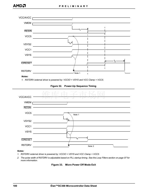
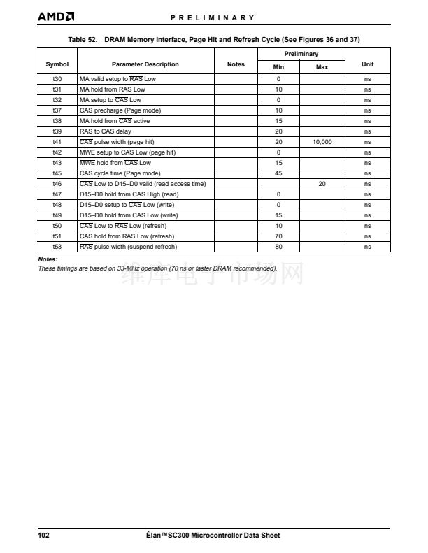
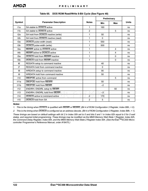
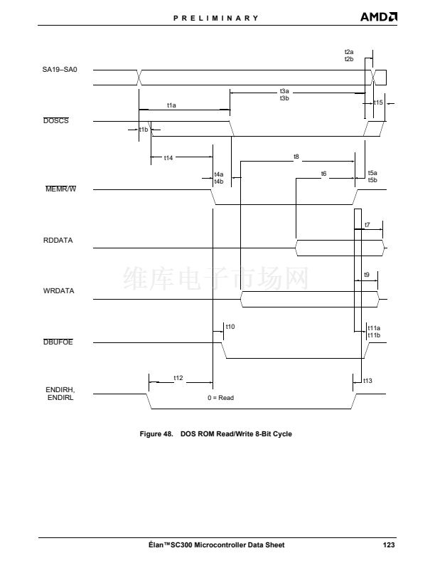
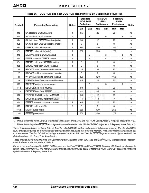
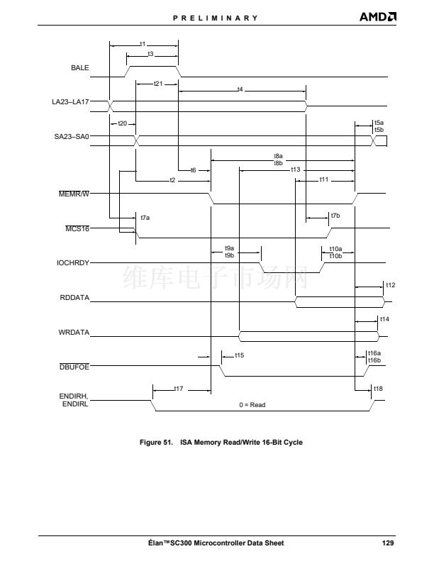
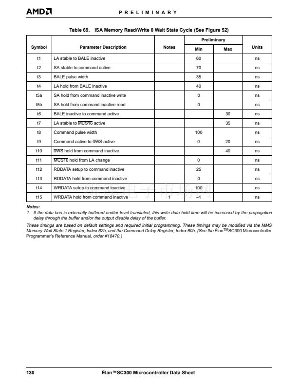
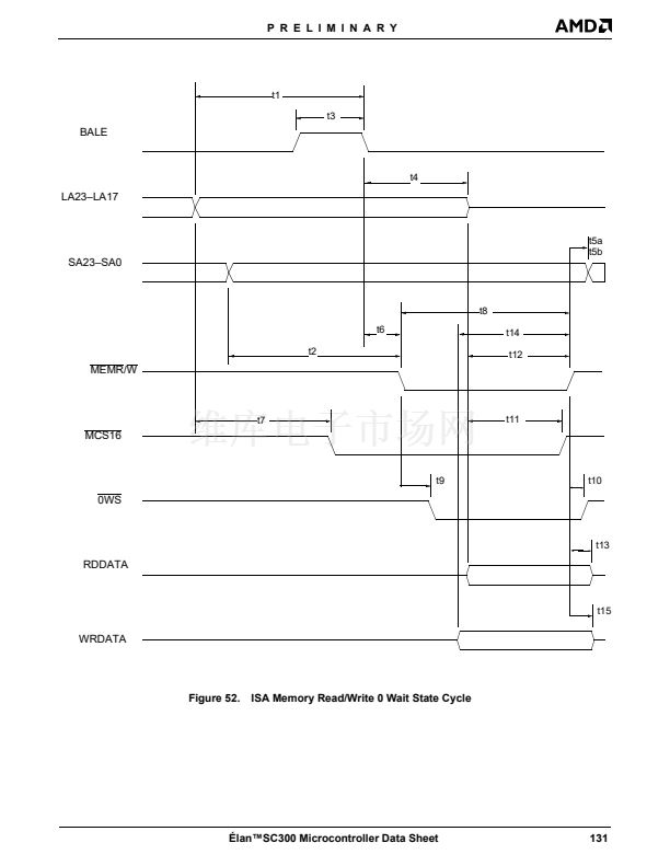
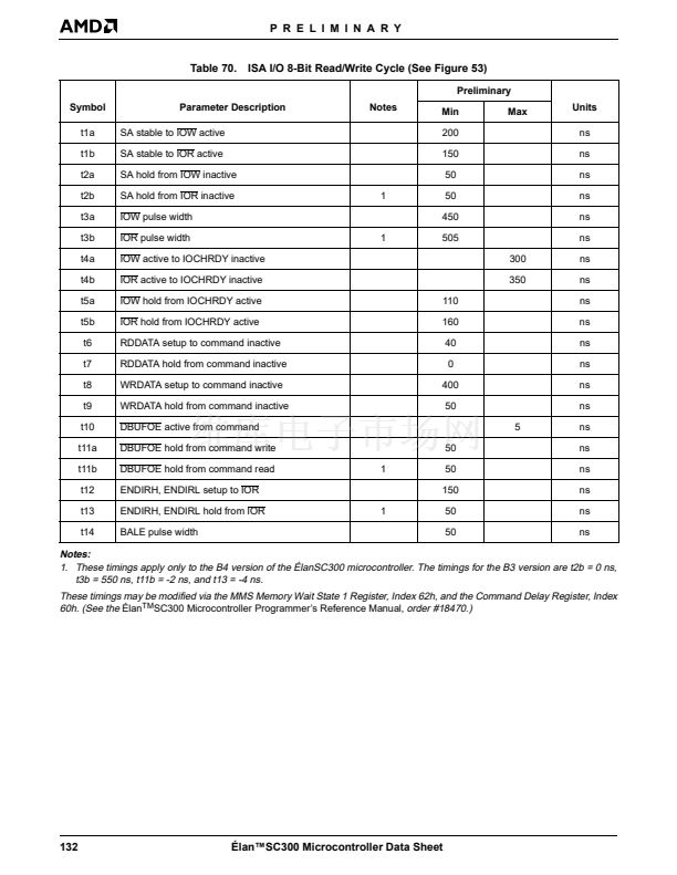
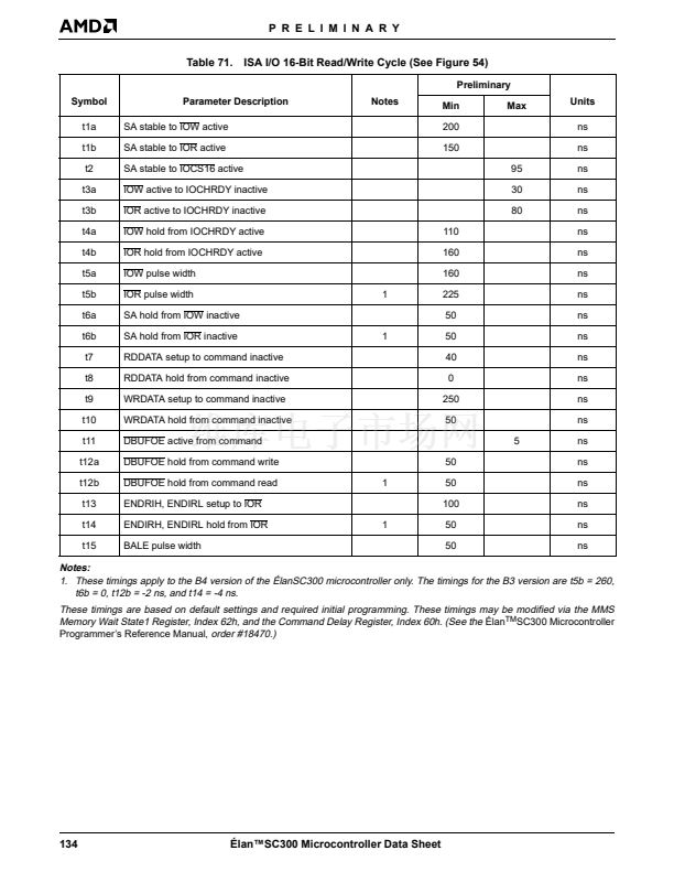
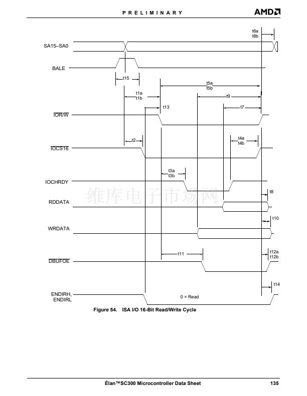
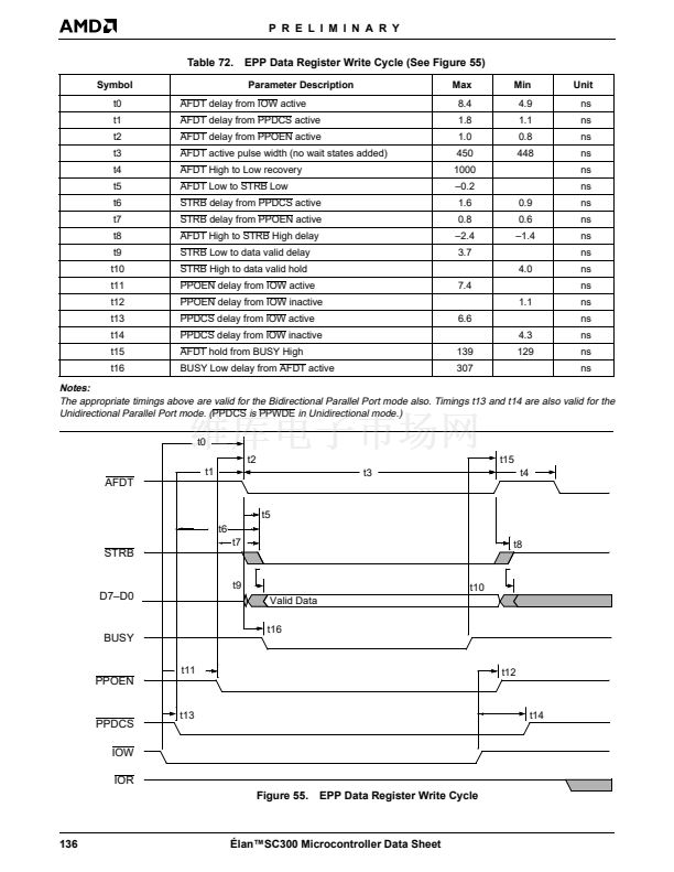
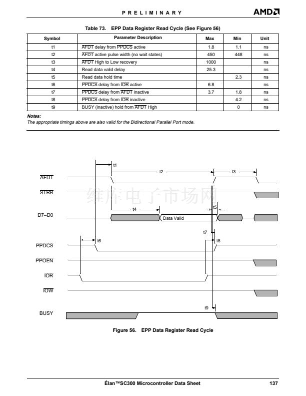
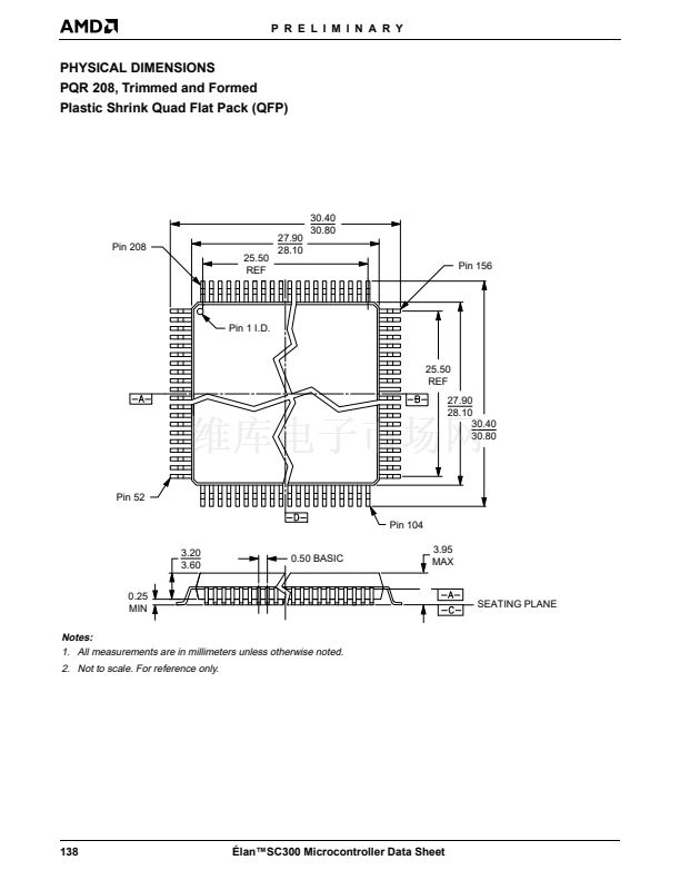
P R E L I M I N A R Y
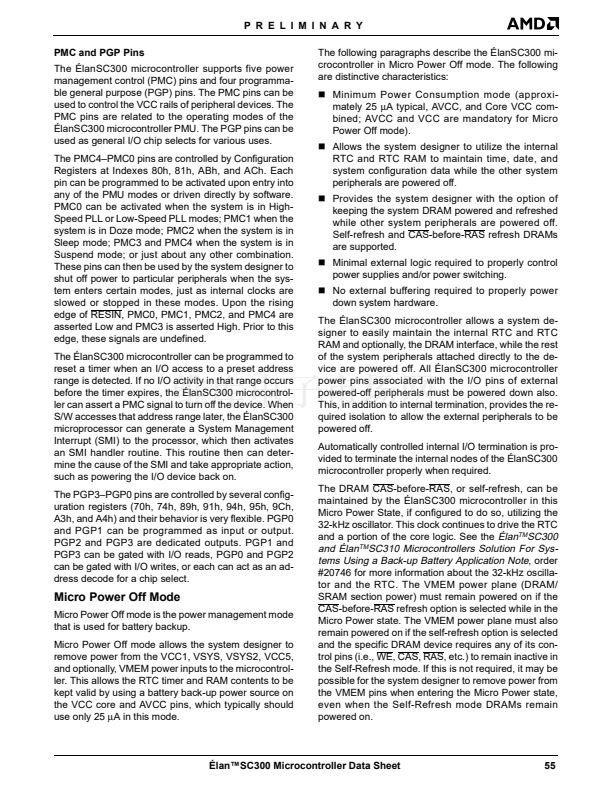
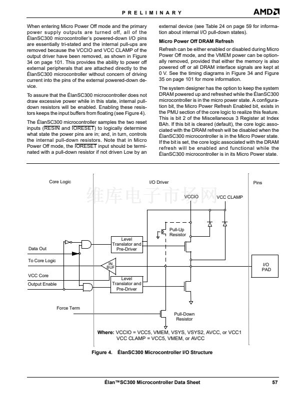
When entering Micro Power Off mode and the primary
power supply outputs are turned off, all of the
脡lanSC300 microcontroller鈥檚 powered-down I/O pins
are essentially tri-stated and the internal pull-ups are
removed because the VCCIO and VCC CLAMP of the
output driver have been removed, as shown in Figure
34 on page 101. This provides the ability to power off
external peripherals that are attached directly to the
脡lanSC300 microcontroller without concern of driving
current into the pins of the external powered-down de-
vice.
To assure that the 脡lanSC300 microcontroller does not
draw excessive power while in this state, internal pull-
down resistors will be enabled. Enabling these resis-
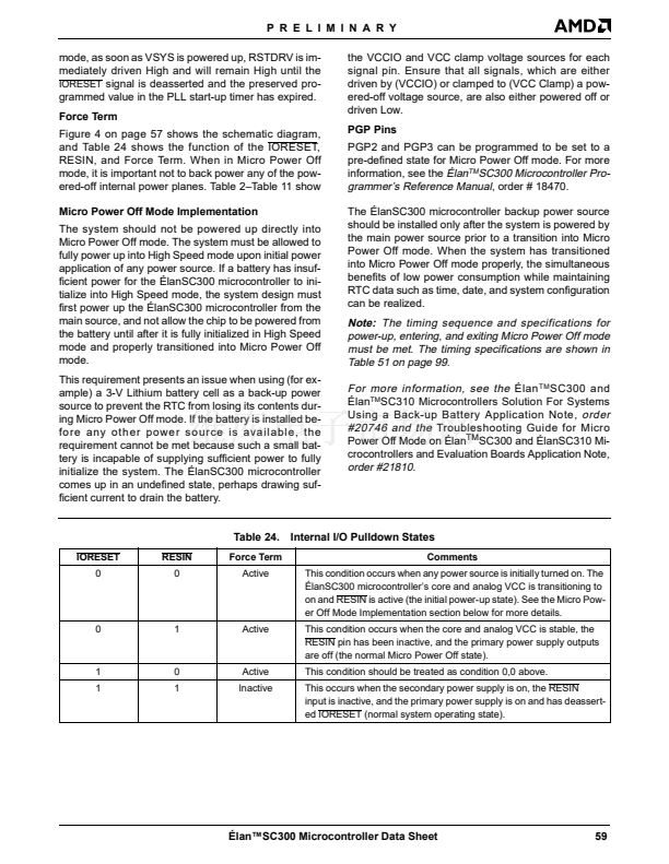
tors keeps the input buffers from floating (see Figure 4).
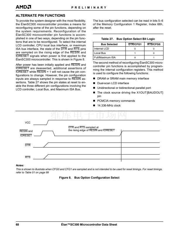
The 脡lanSC300 microcontroller samples the two reset
inputs (RESIN and IORESET) to logically determine
what state the power pins are in; and, in turn, controls
the internal pull-down resistors. Note that in Micro
Power Off mode, the IORESET input should be termi-
nated with a pull-down resistor if not driven Low by an
external device (see Table 24 on page 59 for informa-
tion about internal I/O pull-down states).
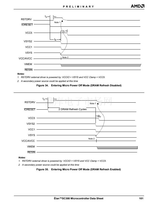
Micro Power Off DRAM Refresh
Refresh can be either enabled or disabled during Micro
Power Off mode, and the VMEM power can be option-
ally removed, provided that either the memory is also
powered off or all DRAM interface signals are kept at
0 V. See the timing diagrams in Figure 34 and Figure
35 on page 101 for more information.
The system designer has the option to keep the system
DRAM powered up and refreshed while the 脡lanSC300
microcontroller is in the micro power state. A configura-
tion bit, the Micro Power Refresh Enabled bit, exists in
the PMU section of the core logic to realize this feature.
This is bit 2 of the Miscellaneous 3 Register at Index
BAh. If this bit is cleared (default), the core logic asso-
ciated with the DRAM refresh will be disabled when the
脡lanSC300 microcontroller is in the Micro Power state.
If the bit is set, the core logic associated with the DRAM
refresh will be enabled and functional while the
脡lanSC300 microcontroller is in its Micro Power state.
Core Logic
I/O Driver
VCCIO
VCC CLAMP
Pins
Pull-Up
Resistor
Data Out
To Core Logic
VCC Core
Output Enable
Level
Translator and
Pre-Driver
IN
BUF
I/O
PAD
Level
Translator and
Pre-Driver
Force Term
Pull-Down
Resistor
Where:
VCCIO = VCC5, VMEM, VSYS, VSYS2, AVCC, or VCC1
VCC CLAMP = VCC5, VMEM, or AVCC
Figure 4.
脡lanSC300 Microcontroller I/O Structure
脡lan鈩C300 Microcontroller Data Sheet
57


 1
1
 2
2
 3
3
 4
4
 5
5
 6
6
 7
7
 8
8
 9
9
 10
10
 11
11
 12
12
 13
13
 14
14
 15
15
 16
16
 17
17
 18
18
 19
19
 20
20
 21
21
 22
22
 23
23
 24
24
 25
25
 26
26
 27
27
 28
28
 29
29
 30
30
 31
31
 32
32
 33
33
 34
34
 35
35
 36
36
 37
37
 38
38
 39
39
 40
40
 41
41
 42
42
 43
43
 44
44
 45
45
 46
46
 47
47
 48
48
 49
49
 50
50
 51
51
 52
52
 53
53
 54
54
 55
55
 56
56
 57
57
 58
58
 59
59
 60
60
 61
61
 62
62
 63
63
 64
64
 65
65
 66
66
 67
67
 68
68
 69
69
 70
70
 71
71
 72
72
 73
73
 74
74
 75
75
 76
76
 77
77
 78
78
 79
79
 80
80
 81
81
 82
82
 83
83
 84
84
 85
85
 86
86
 87
87
 88
88
 89
89
 90
90
 91
91
 92
92
 93
93
 94
94
 95
95
 96
96
 97
97
 98
98
 99
99
 100
100
 101
101
 102
102
 103
103
 104
104
 105
105
 106
106
 107
107
 108
108
 109
109
 110
110
 111
111
 112
112
 113
113
 114
114
 115
115
 116
116
 117
117
 118
118
 119
119
 120
120
 121
121
 122
122
 123
123
 124
124
 125
125
 126
126
 127
127
 128
128
 129
129
 130
130
 131
131
 132
132
 133
133
 134
134
 135
135
 136
136
 137
137
 138
138
 139
139
