P R E L I M I N A R Y
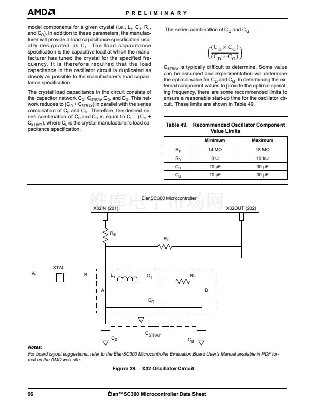
LOOP FILTERS
Each of the Phase-Locked Loops (PLLs) in the
脡lanSC300 microcontroller requires an external Loop
Filter. Figure 30 describes each of the Loop Filters and
the recommended component values. The recom-
mended component values are shown in Table 50.
The system designer shall include the pads on the
printed circuit board to accommodate the future instal-
lation/change of C2 and R1. This is recommended be-
cause the PLL performance can be affected by the
physical circuit board design. In addition, future revi-
sions of the 脡lanSC300 microcontroller with a modified
PLL design may require the addition of these compo-
nents to the system board.
The component value(s) of the Loop Filter directly af-
fect the acquisition (start up) time of the PLL circuit.
With the values recommended, the approximate acqui-
sition time is 200 ms. Therefore, the system designer
should program the Clock Control Register at Index
8Fh appropriately. Bits 0, 1, and 2 set the PLL restart
delay time. When the PLLs are shut off for any reason
(i.e., power management), the PLL will be allowed an
amount of time equal to that programmed in this regis-
ter to start up before the PLL outputs are enabled for
the internal device logic. A PLL restart delay time of
256 ms should be set in the Clock Control Register.
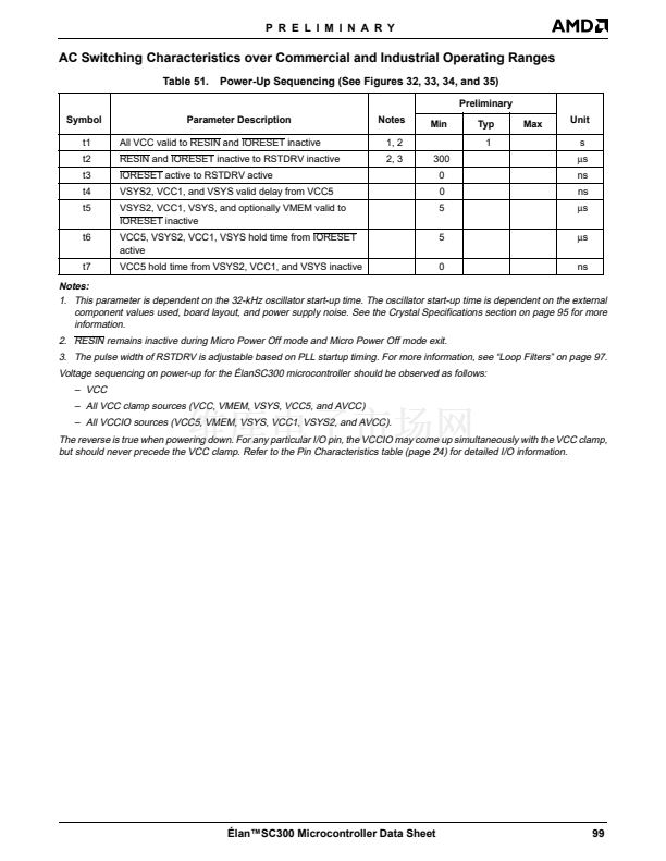
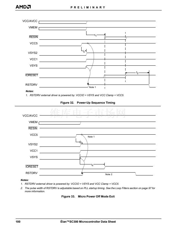
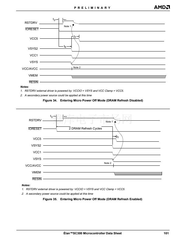
The pulse width of the RSTDRV signal is adjustable
based on the PLL start-up timing. See the timing spec-
ifications in Table 51 and Figure 32鈥揊igure 35.
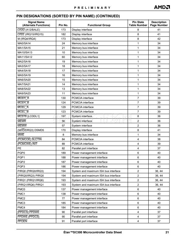
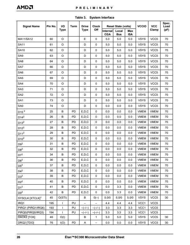
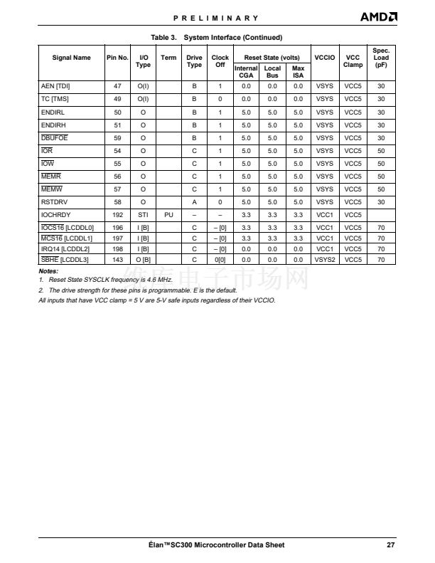
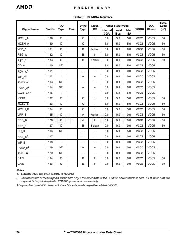
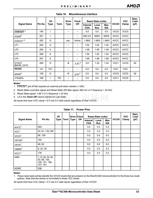
Table 10 on page 33 shows the pin characteristics for
the Loop Filters, including the reset voltage level of
each pin when RESIN is active.
For more information about Loop Filters, see the
Trou-
bleshooting Guide for Micro Power Off Mode on the
脡lan
TM
SC300 and ElanSC310 Microcontrollers and
Evaluation Boards Application Note,
order #21810.
LFx
R
1
C
2
C
1
Figure 30.
Loop-Filter Component
Table 50. Loop-Filter Component Values
LFx
1
2
3
4
R
1
0
0
0
0
C
1
0.47
碌F
0.47
碌F
0.47
碌F
0.47
碌F
C
2
Not Installed
Not Installed
Not Installed
Not Installed
Notes:
1. When the PLL is on, V
LFx
should be approximately be-
tween 1 V and 2 V.
脡lan鈩C300 Microcontroller Data Sheet
97


 1
1
 2
2
 3
3
 4
4
 5
5
 6
6
 7
7
 8
8
 9
9
 10
10
 11
11
 12
12
 13
13
 14
14
 15
15
 16
16
 17
17
 18
18
 19
19
 20
20
 21
21
 22
22
 23
23
 24
24
 25
25
 26
26
 27
27
 28
28
 29
29
 30
30
 31
31
 32
32
 33
33
 34
34
 35
35
 36
36
 37
37
 38
38
 39
39
 40
40
 41
41
 42
42
 43
43
 44
44
 45
45
 46
46
 47
47
 48
48
 49
49
 50
50
 51
51
 52
52
 53
53
 54
54
 55
55
 56
56
 57
57
 58
58
 59
59
 60
60
 61
61
 62
62
 63
63
 64
64
 65
65
 66
66
 67
67
 68
68
 69
69
 70
70
 71
71
 72
72
 73
73
 74
74
 75
75
 76
76
 77
77
 78
78
 79
79
 80
80
 81
81
 82
82
 83
83
 84
84
 85
85
 86
86
 87
87
 88
88
 89
89
 90
90
 91
91
 92
92
 93
93
 94
94
 95
95
 96
96
 97
97
 98
98
 99
99
 100
100
 101
101
 102
102
 103
103
 104
104
 105
105
 106
106
 107
107
 108
108
 109
109
 110
110
 111
111
 112
112
 113
113
 114
114
 115
115
 116
116
 117
117
 118
118
 119
119
 120
120
 121
121
 122
122
 123
123
 124
124
 125
125
 126
126
 127
127
 128
128
 129
129
 130
130
 131
131
 132
132
 133
133
 134
134
 135
135
 136
136
 137
137
 138
138
 139
139
