P R E L I M I N A R Y
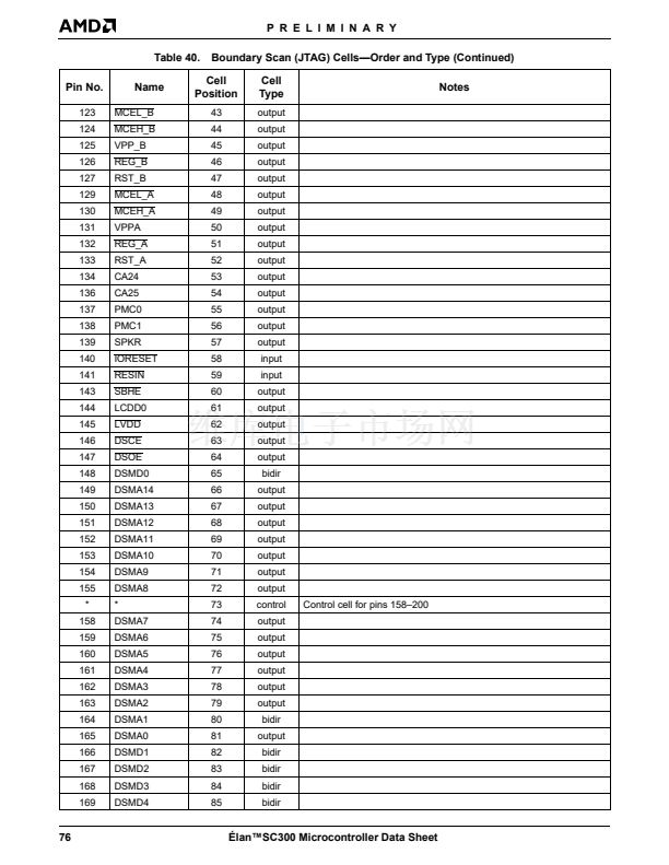
AC SWITCHING CHARACTERISTICS AND WAVEFORMS
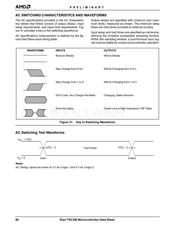
The AC specifications provided in the AC characteris-
tics tables that follow consist of output delays, input
setup requirements, and input hold requirements. Fig-
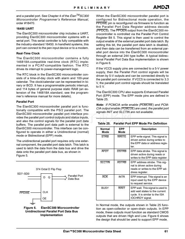
ure 31 provides a key to the switching waveforms.
AC specifications measurement is defined by the fig-
ures that follow each timing table.
Output delays are specified with minimum and maxi-
mum limits, measured as shown. The minimum delay
times are hold times provided to external circuitry.
Input setup and hold times are specified as minimums,
defining the smallest acceptable sampling window.
Within the sampling window, a synchronous input sig-
nal must be stable for correct microcontroller operation.
OUTPUTS
Will be Steady
WAVEFORMS
INPUTS
Must be Steady
May Change from H to L
Will be Changing from H to L
May Change from L to H
Will be Changing from L to H
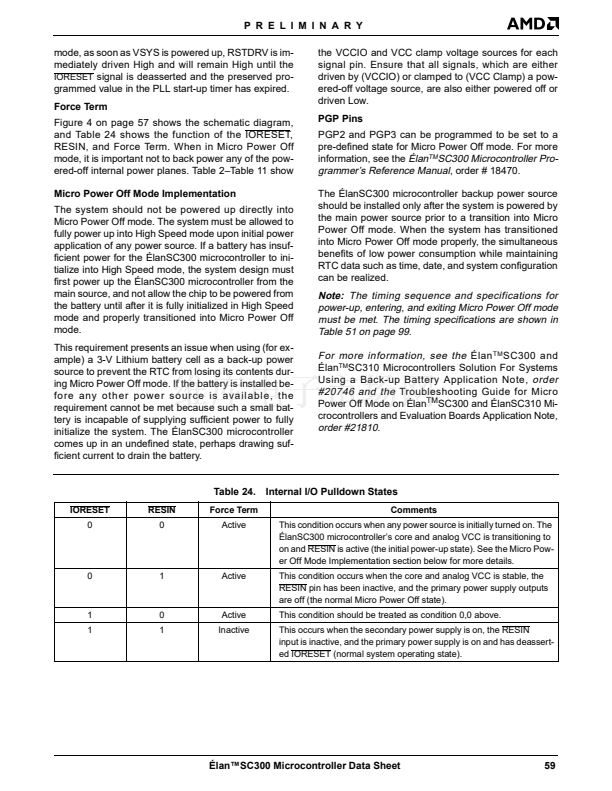
Don鈥檛 Care, Any Change Permitted
Changing, State Unknown
Does Not Apply
Center Line is High-Impedance 鈥淥ff鈥?State
Figure 31. Key to Switching Waveforms
AC Switching Test Waveforms
V
IH
= VCC
VCC
梅
2
Test Points
VCC
梅
2
V
IL
= 0
Input
Output
Notes:
AC Testing: Inputs are driven at 3 V for a logic 1 and 0 V for a logic 0.
98
脡lan鈩C300 Microcontroller Data Sheet


 1
1
 2
2
 3
3
 4
4
 5
5
 6
6
 7
7
 8
8
 9
9
 10
10
 11
11
 12
12
 13
13
 14
14
 15
15
 16
16
 17
17
 18
18
 19
19
 20
20
 21
21
 22
22
 23
23
 24
24
 25
25
 26
26
 27
27
 28
28
 29
29
 30
30
 31
31
 32
32
 33
33
 34
34
 35
35
 36
36
 37
37
 38
38
 39
39
 40
40
 41
41
 42
42
 43
43
 44
44
 45
45
 46
46
 47
47
 48
48
 49
49
 50
50
 51
51
 52
52
 53
53
 54
54
 55
55
 56
56
 57
57
 58
58
 59
59
 60
60
 61
61
 62
62
 63
63
 64
64
 65
65
 66
66
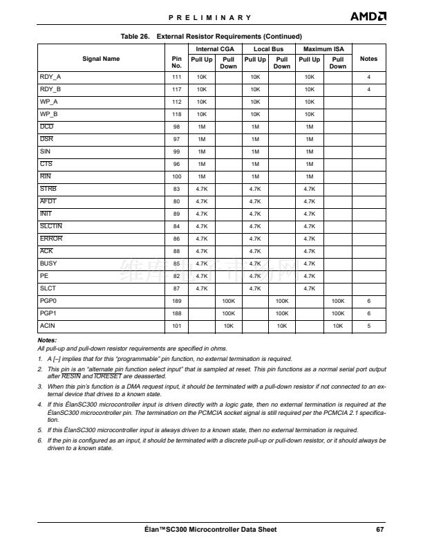 67
67
 68
68
 69
69
 70
70
 71
71
 72
72
 73
73
 74
74
 75
75
 76
76
 77
77
 78
78
 79
79
 80
80
 81
81
 82
82
 83
83
 84
84
 85
85
 86
86
 87
87
 88
88
 89
89
 90
90
 91
91
 92
92
 93
93
 94
94
 95
95
 96
96
 97
97
 98
98
 99
99
 100
100
 101
101
 102
102
 103
103
 104
104
 105
105
 106
106
 107
107
 108
108
 109
109
 110
110
 111
111
 112
112
 113
113
 114
114
 115
115
 116
116
 117
117
 118
118
 119
119
 120
120
 121
121
 122
122
 123
123
 124
124
 125
125
 126
126
 127
127
 128
128
 129
129
 130
130
 131
131
 132
132
 133
133
 134
134
 135
135
 136
136
 137
137
 138
138
 139
139
