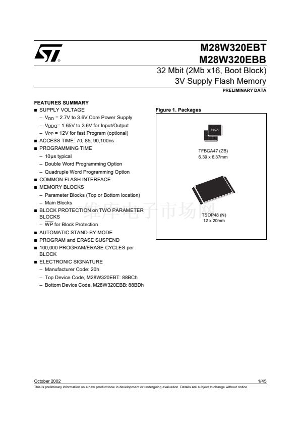
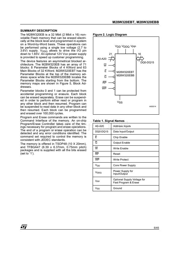
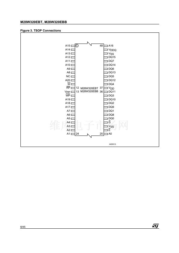
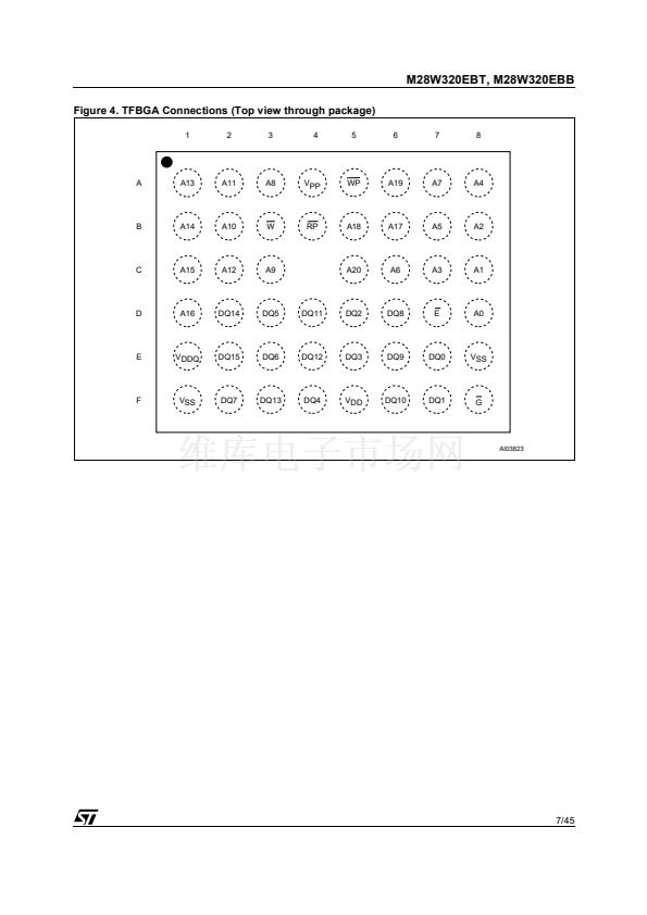
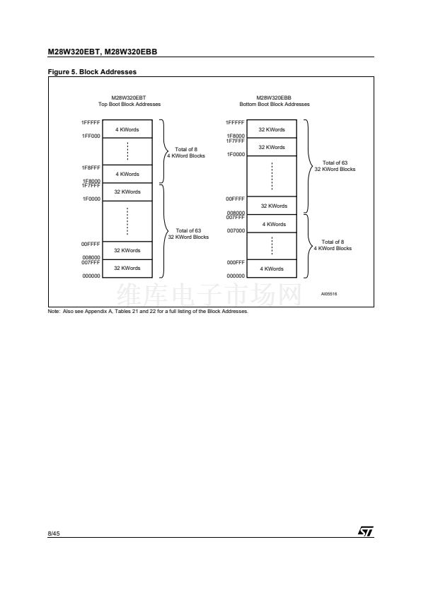
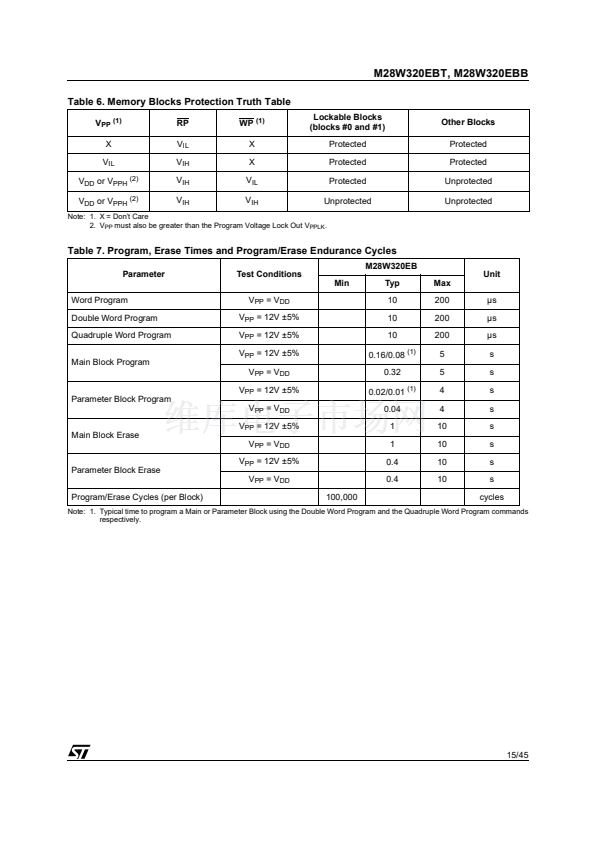
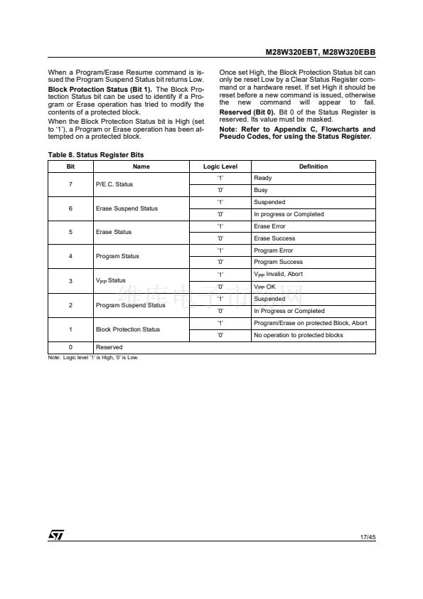
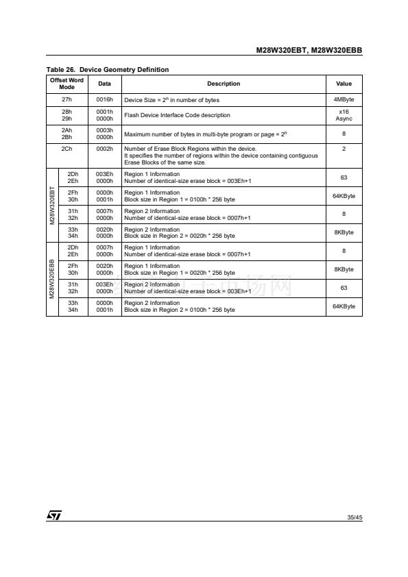
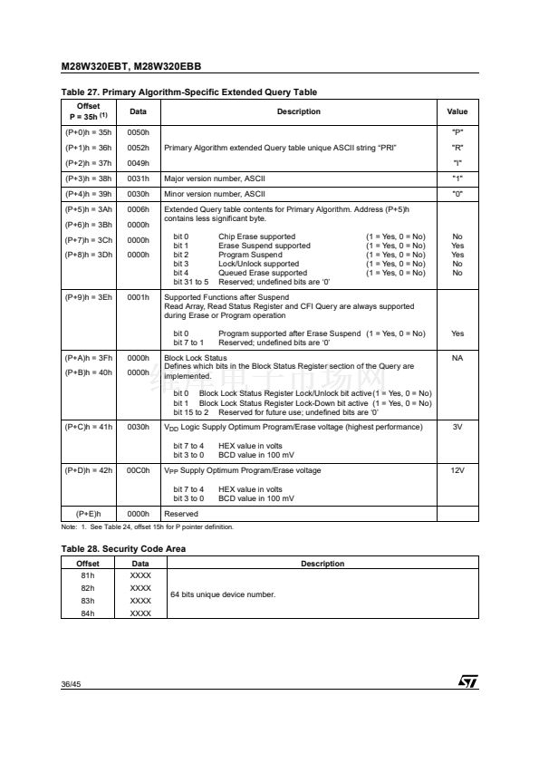
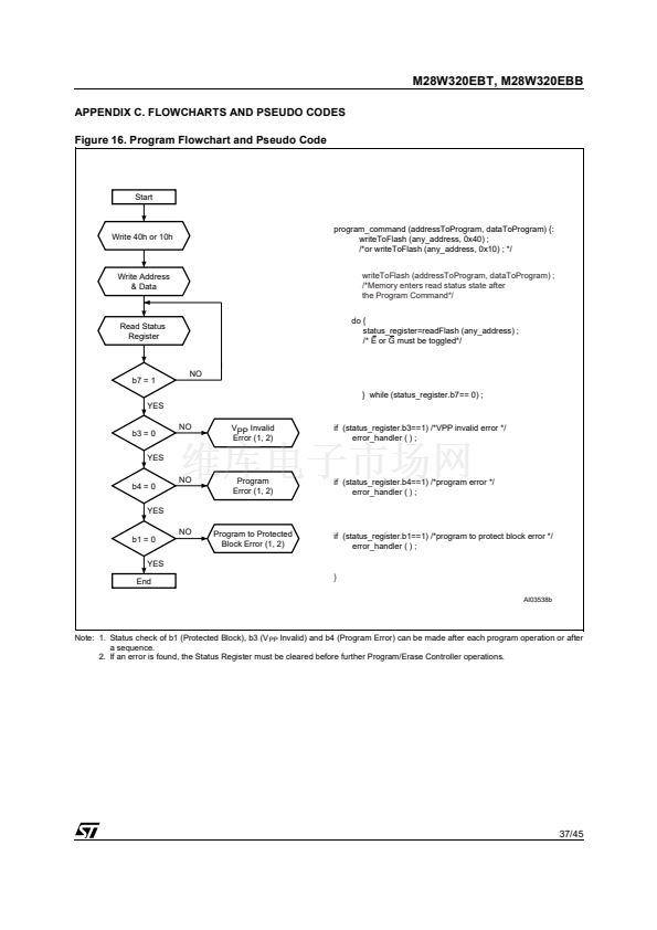
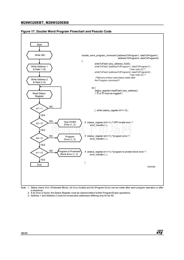
M28W320EBT, M28W320EBB
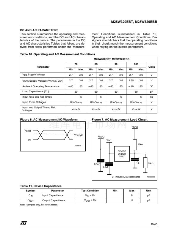
DC AND AC PARAMETERS
This section summarizes the operating and mea-
surement conditions, and the DC and AC charac-
teristics of the device. The parameters in the DC
and AC characteristics Tables that follow, are de-
rived from tests performed under the Measure-
ment Conditions summarized in Table 10,
Operating and AC Measurement Conditions. De-
signers should check that the operating conditions
in their circuit match the measurement conditions
when relying on the quoted parameters.
Table 10. Operating and AC Measurement Conditions
M28W320EBT, M28W320EBB
70
Parameter
Min
V
DD
Supply Voltage
V
DDQ
Supply Voltage (V
DDQ
鈮?/div>
V
DD
)
Ambient Operating Temperature
Load Capacitance (C
L
)
Input Rise and Fall Times
Input Pulse Voltages
Input and Output Timing Ref.
Voltages
2.7
2.7
鈥?40
50
5
0 to V
DDQ
V
DDQ
/2
Max
3.6
3.6
85
Min
2.7
2.7
鈥?40
50
5
0 to V
DDQ
V
DDQ
/2
Max
3.6
3.6
85
Min
2.7
2.7
鈥?40
50
5
0 to V
DDQ
V
DDQ
/2
Max
3.6
3.6
85
Min
2.7
1.65
鈥?40
50
5
0 to V
DDQ
V
DDQ
/2
Max
3.6
3.6
85
V
V
掳C
pF
ns
V
V
85
90
100
Units
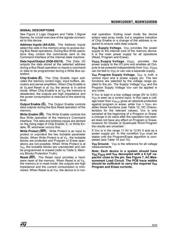
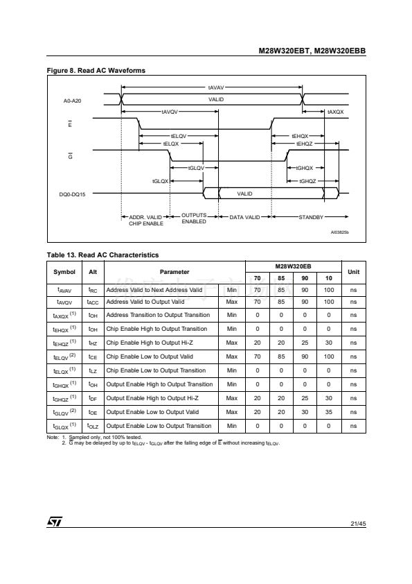
Figure 6. AC Measurement I/O Waveform
Figure 7. AC Measurement Load Circuit
VDDQ
VDDQ
VDDQ/2
0V
AI00610
VDDQ
VDD
25k鈩?/div>
DEVICE
UNDER
TEST
0.1碌F
0.1碌F
CL
25k鈩?/div>
CL includes JIG capacitance
AI00609C
Table 11. Device Capacitance
Symbol
C
IN
C
OUT
Parameter
Input Capacitance
Output Capacitance
Test Condition
V
IN
= 0V
V
OUT
= 0V
Min
Max
6
12
Unit
pF
pF
Note: Sampled only, not 100% tested.
19/45


 1
1
 2
2
 3
3
 4
4
 5
5
 6
6
 7
7
 8
8
 9
9
 10
10
 11
11
 12
12
 13
13
 14
14
 15
15
 16
16
 17
17
 18
18
 19
19
 20
20
 21
21
 22
22
 23
23
 24
24
 25
25
 26
26
 27
27
 28
28
 29
29
 30
30
 31
31
 32
32
 33
33
 34
34
 35
35
 36
36
 37
37
 38
38
 39
39
 40
40
 41
41
 42
42
 43
43
 44
44
 45
45
