3
Theory of Operation
The HEDS-5500, 5540, 5600,
5640, and HEDM-5500, 5600
translate the rotary motion of a
shaft into either a two- or a three-
channel digital output.
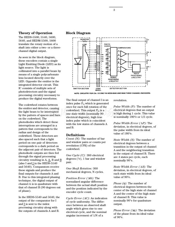
As seen in the block diagram,
these encoders contain a single
Light Emitting Diode (LED) as its
light source. The light is
collimated into a parallel beam by
means of a single polycarbonate
lens located directly over the
LED. Opposite the emitter is the
integrated detector circuit. This
IC consists of multiple sets of
photodetectors and the signal
processing circuitry necessary to
produce the digital waveforms.
The codewheel rotates between
the emitter and detector, causing
the light beam to be interrupted
by the pattern of spaces and bars
on the codewheel. The
photodiodes which detect these
interruptions are arranged in a
pattern that corresponds to the
radius and design of the
codewheel. These detectors are
also spaced such that a light
period on one pair of detectors
corresponds to a dark period on
the adjacent pair of detectors. The
photodiode outputs are then fed
through the signal processing
circuitry resulting in A, A, B and B
(also I and I in the HEDS-5540
and 5640). Comparators receive
these signals and produce the
final outputs for channels A and
B. Due to this integrated phasing
technique, the digital output of
channel A is in quadrature with
that of channel B (90 degrees out
of phase).
In the HEDS-5540 and 5640, the
output of the comparator for I
and I is sent to the index
processing circuitry along with
the outputs of channels A and B.
Block Diagram
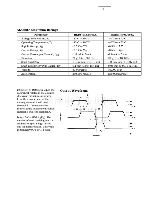
The final output of channel I is an
index pulse P
O
which is generated
once for each full rotation of the
codewheel. This output P
O
is a
one state width (nominally 90
electrical degrees), high true
index pulse which is coincident
with the low states of channels A
and B.
revolution.
Pulse Width (P):
The number of
electrical degrees that an output
is high during 1 cycle. This value
is nominally 180掳e or 1/2 cycle.
Pulse Width Error (
鈭哖):
The
deviation, in electrical degrees, of
the pulse width from its ideal
value of 180掳e.
State Width (S):
The number of
electrical degrees between a
transition in the output of channel
A and the neighboring transition
in the output of channel B. There
are 4 states per cycle, each
nominally 90掳e.
State Width Error (
鈭哠):
The
deviation, in electrical degrees, of
each state width from its ideal
value of 90掳e.
Phase (蠁):
The number of
electrical degrees between the
center of the high state of channel
A and the center of the high state
of channel B. This value is
nominally 90掳e for quadrature
output.
Phase Error (鈭喯?:
The deviation
of the phase from its ideal value
of 90掳e.
Definitions
Count (N):
The number of bar
and window pairs or counts per
revolution (CPR) of the
codewheel.
One Cycle (C):
360 electrical
degrees (掳e), 1 bar and window
pair.
One Shaft Rotation:
360
mechanical degrees, N cycles.
Position Error (
鈭單?:
The
normalized angular difference
between the actual shaft position
and the position indicated by the
encoder cycle count.
Cycle Error (
鈭?/div>
C):
An indication
of cycle uniformity. The differ-
ence between an observed shaft
angle which gives rise to one
electrical cycle, and the nominal
angular increment of 1/N of a


 1
1
 2
2
 3
3
 4
4
 5
5
 6
6
 7
7
 8
8
 9
9
 10
10
 11
11
 12
12
 13
13
 14
14
 15
15
