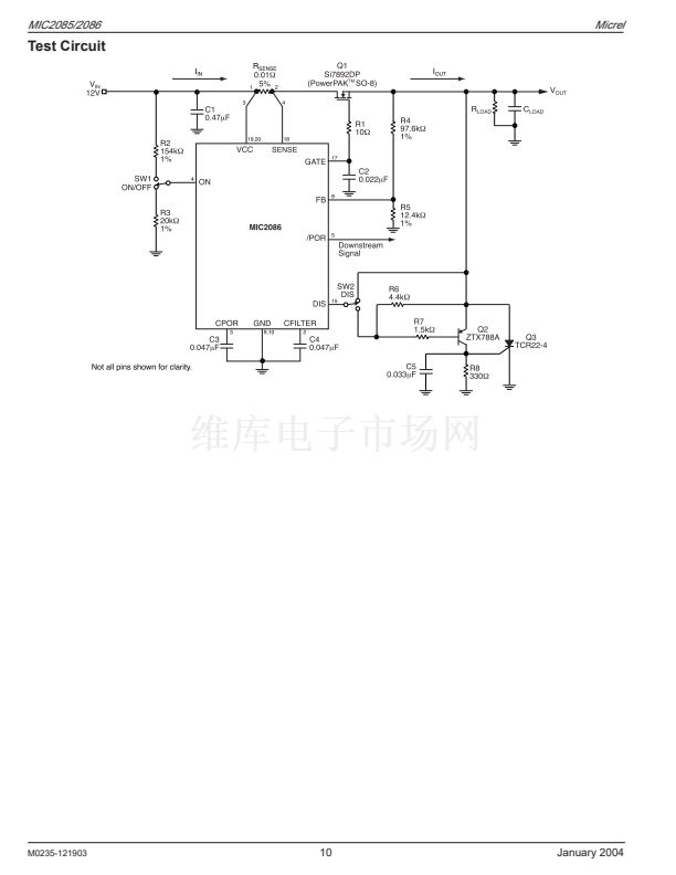
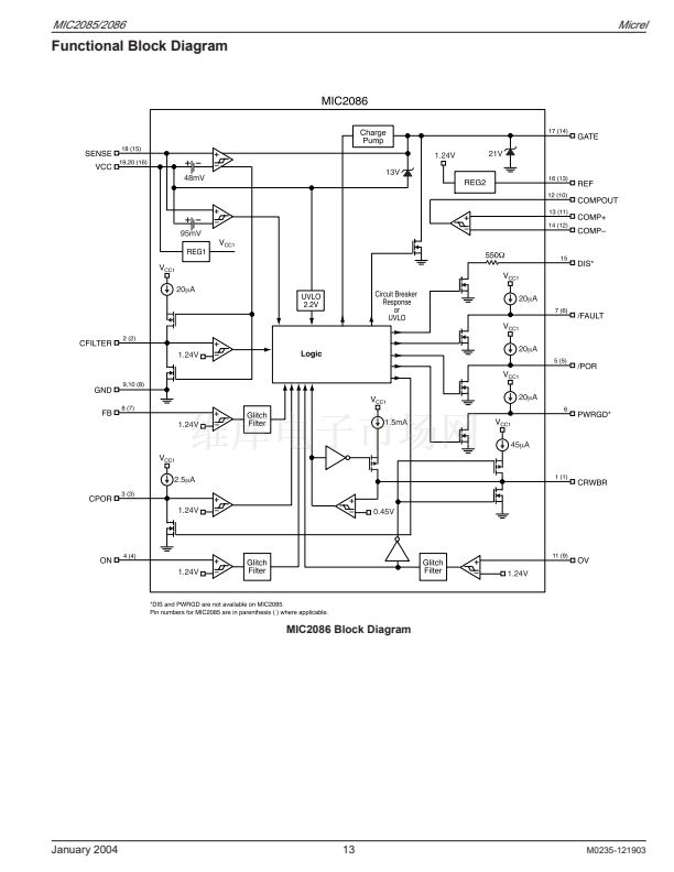
MIC2085/2086
Micrel
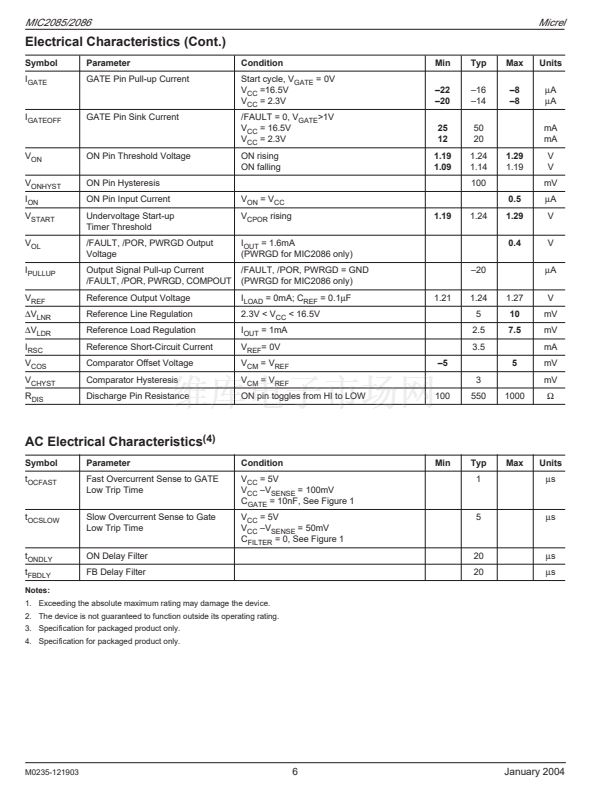
where V
TRIPSLOW
is the current limit slow trip threshold found
in the electrical table and R
SENSE
is the selected value that
will set the desired current limit. There are two basic start-up
modes for the MIC2085/86: 1)Start-up dominated by load
capacitance and 2)start-up dominated by total gate capaci-
tance. The magnitude of the inrush current delivered to the
load will determine the dominant mode. If the inrush current
is greater than the programmed current limit (I
LIM
), then load
capacitance is dominant. Otherwise, gate capacitance is
dominant. The expected inrush current may be calculated
using the following equation:
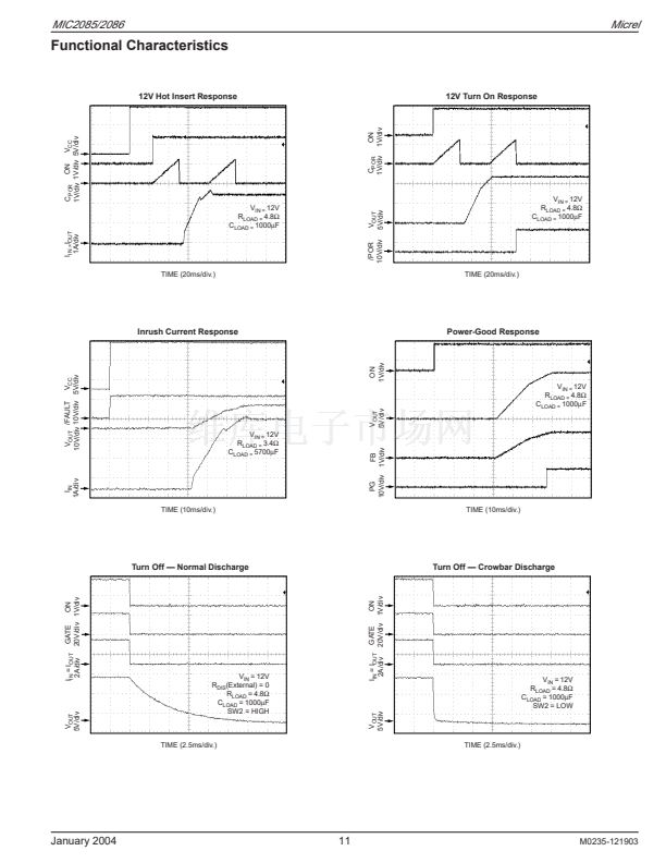
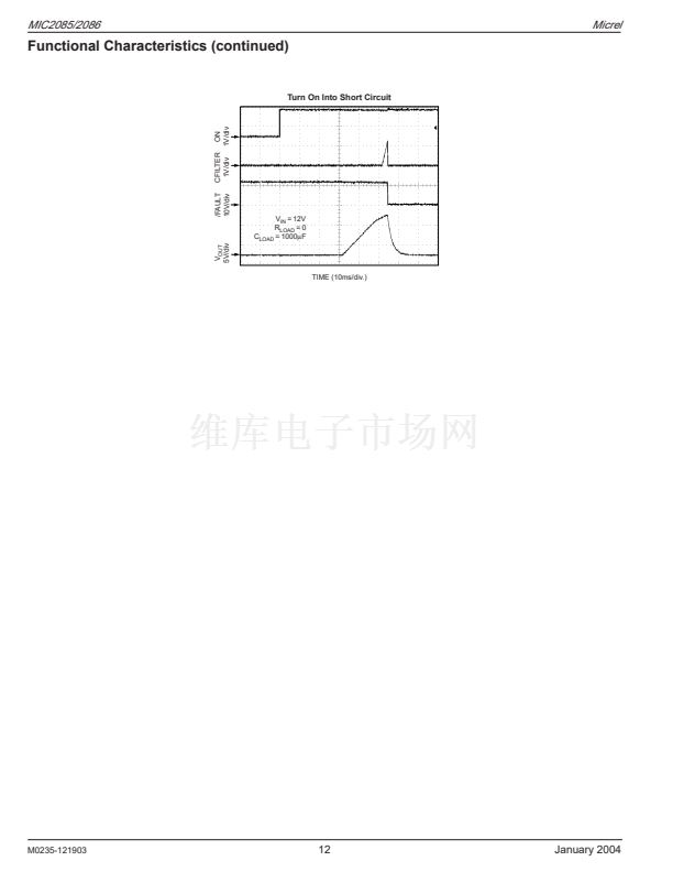
Functional Description
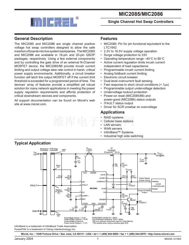
Hot Swap Insertion
When circuit boards are inserted into live system backplanes
and supply voltages, high inrush currents can result due to
the charging of bulk capacitance that resides across the
supply pins of the circuit board. This inrush current, although
transient in nature, may be high enough to cause permanent
damage to on-board components or may cause the system鈥檚
supply voltages to go out of regulation during the transient
period which may result in system failures. The MIC2085/86
acts as a controller for external N-Channel MOSFET devices
in which the gate drive is controlled to provide inrush current
limiting and output voltage slew rate control during hot plug
insertions.
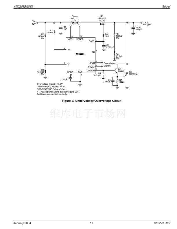
Power Supply
VCC is the supply input to the MIC2085/86 controller with a
voltage range of 2.3V to 16.5V. The VCC input can withstand
transient spikes up to 33V. In order to help suppress tran-
sients and ensure stability of the supply voltage, a capacitor
of 1.0碌F to 10碌F from VCC to ground is recommended.
Alternatively, a low pass filter, shown in the typical application
circuit, can be used to eliminate high frequency oscillations as
well as help suppress transient spikes.
Start-Up Cycle
When the voltage on the ON pin rises above its threshold of
1.24V, the MIC2085/86 first checks that its supply (V
CC
) is
above the UVLO threshold. If so, the device is enabled and
an internal 2碌A current source begins charging capacitor
C
POR
to 1.24V to initiate a start-up sequence (i.e., start-up
delay times out). Once the start-up delay (t
START
) elapses,
CPOR is pulled immediately to ground and a 15碌A current
source begins charging the GATE output to drive the external
MOSFET that switches V
IN
to V
OUT
. The programmed start-
up delay is calculated using the following equation:
INRUSH
鈮?/div>
I
GATE
脳
C
LOAD
C
GATE
鈮?/div>
15
碌
A
脳
C
LOAD
C
GATE
(3)
where I
GATE
is the GATE pin pull-up current, C
LOAD
is the
load capacitance, and C
GATE
is the total GATE capacitance
(C
ISS
of the external MOSFET and any external capacitor
connected from the MIC2085/86 GATE pin to ground).
Load Capacitance Dominated Start-Up
In this case, the load capacitance, C
LOAD
, is large enough to
cause the inrush current to exceed the programmed current
limit but is less than the fast-trip threshold (or the fast-trip
threshold is disabled, 鈥楳鈥?option). During start-up under this
condition, the load current is regulated at the programmed
current limit value (I
LIM
) and held constant until the output
voltage rises to its final value. The output slew rate and
equivalent GATE voltage slew rate is computed by the
following equation:
Output Voltage Slew Rate, dV
OUT
/dt
=
I
LIM
C
LOAD
(4)
t
START
=
C
POR
脳
V
TH
I
CPOR
鈮?/div>
0.62
脳
C
POR
(
碌
F)
(1)
where V
TH
, the POR delay threshold, is 1.24V, and I
CPOR
,
the POR timer current, is 2碌A. As the GATE voltage contin-
ues ramping toward its final value (V
CC
+ V
GS
) at a defined
slew rate (See
鈥淟oad Capacitance鈥?鈥淕ate Capacitance Domi-
nated Start-Up鈥?/div>
sections), a second CPOR timing cycle
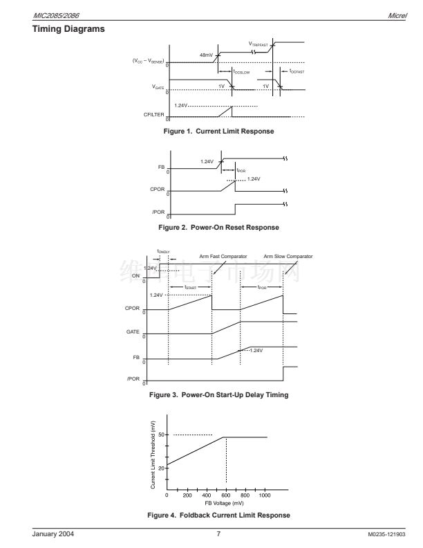
begins if: 1)/FAULT is high and 2)CFILTER is low (i.e., not
an overvoltage, undervoltage lockout, or overcurrent state).
This second timing cycle, t
POR
, starts when the voltage at the
FB pin exceeds its threshold (V
FB
) indicating that the output
voltage is valid. The time period t
POR
is equivalent to t
START
and sets the interval for the /POR to go Low-to-High after
鈥減ower is good鈥?(See Figure 2 of
鈥淭iming Diagrams鈥?/div>
). Active
current regulation is employed to limit the inrush current
transient response during start-up by regulating the load
current at the programmed current limit value (See
鈥淐urrent
Limiting and Dual-Level Circuit Breaker鈥?/div>
section). The fol-
lowing equation is used to determine the nominal current
limit value:
I
LIM
=
M0235-121903
where I
LIM
is the programmed current limit value. Conse-
quently, the value of C
FILTER
must be selected to ensure that
the overcurrent response time, t
OCSLOW
, exceeds the time
needed for the output to reach its final value. For example,
given a MOSFET with an input capacitance C
ISS
= C
GATE
=
4700pF, C
LOAD
is 2200碌F, and I
LIMIT
is set to 6A with a 12V
input, then the load capacitance dominates as determined by
the calculated INRUSH > I
LIM
. Therefore, the output voltage
slew rate determined from Equation 4 is:
Output Voltage Slew Rate, dV
OUT
/dt
=
6A
V
=
2.73
2200
碌
F
ms
and the resulting t
OCSLOW
needed to achieve a 12V output is
approximately 4.5ms. (See
鈥淧ower-On Reset, Start-Up, and
Overcurrent Timer Delays鈥?/div>
section to calculate t
OCSLOW
.)
GATE Capacitance Dominated Start-Up
In this case, the value of the load capacitance relative to the
GATE capacitance is small enough such that the load current
during start-up never exceeds the current limit threshold as
determined by Equation 3. The minimum value of C
GATE
that
will ensure that the current limit is never exceeded is given by
the equation below:
I
C
GATE
(min)
=
GATE
脳
C
LOAD
I
LIM
(5)
V
TRIPSLOW
48mV
=
R
SENSE
R
SENSE
(2)
14
January 2004
MIC2085-LBQS 产品属性
196
集成电路 (IC)
PMIC - 热交换
-
热交换控制器
通用型 Infiniband?
无
-
2.3 V ~ 16.5 V
-40°C ~ 85°C
表面贴装
16-SSOP(0.154",3.90mm 宽)
16-QSOP
管件
MIC2085-LBQS相关型号PDF文件下载
-
型号
版本
描述
厂商
下载
-
英文版
SINGLE CHANNEL HIGH CURRENT LOW VOLTAGE, PROTECTED POWER DIS...
-
英文版
SINGLE CHANNEL HIGH CURRENT LOW VOLTAGE, PROTECTED POWER DIS...
MICREL [Mi...
-
英文版
Precision IttyBitty Thermal Supervisor
-
英文版
Low-Cost IttyBitty Thermal Sensor IttyBitty
-
英文版
Micrel Semiconductor [Two-Zone Thermal Supervisor Advance I...
-
英文版
Adjustable Current Limit Power Distribution Switch
-
英文版
Adjustable Current Limit Power Distribution Switch
MICREL [Mi...
-
英文版
USB Power Controller Advance Information
-
英文版
USB Power Controller Advance Information
MICREL [Mi...
-
英文版
USB Power Controller Advance Information
-
英文版
USB Power Controller Advance Information
MICREL [Mi...
-
英文版
Adjustable Current Limit Power Distribution Switch
-
英文版
Adjustable Current Limit Power Distribution Switch
MICREL [Mi...
-
英文版
Single-Channel Power Distribution Switch Preliminary Informa...
-
英文版
Single-Channel Power Distribution Switch Preliminary Informa...
MICREL [Mi...
-
英文版
Dual-Channel Power Distribution Switch Preliminary Informati...
-
英文版
Dual-Channel Power Distribution Switch Preliminary Informati...
MICREL [Mi...
-
英文版
Quad USB Power Distribution Switch Preliminary Information
-
英文版
Quad USB Power Distribution Switch Preliminary Information
MICREL [Mi...
-
英文版
SINGLE CHANNEL HIGH CURRENT LOW VOLTAGE, PROTECTED POWER DIS...


 1
1
 2
2
 3
3
 4
4
 5
5
 6
6
 7
7
 8
8
 9
9
 10
10
 11
11
 12
12
 13
13
 14
14
 15
15
 16
16
 17
17
 18
18
 19
19
 20
20
 21
21
 22
22
 23
23
 24
24
 25
25
 26
26
 27
27
 28
28
