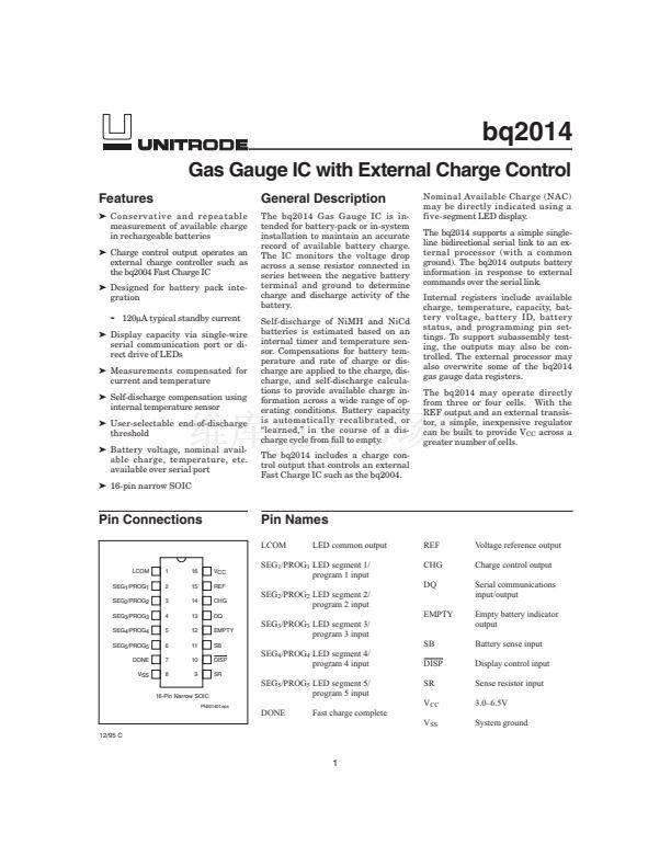
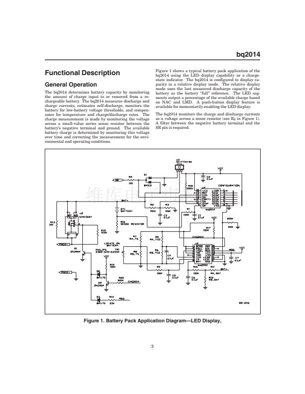
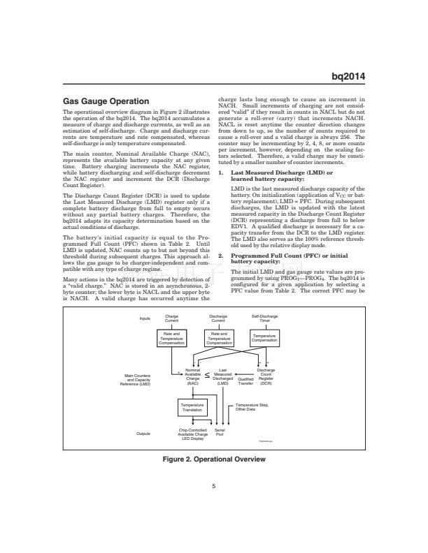
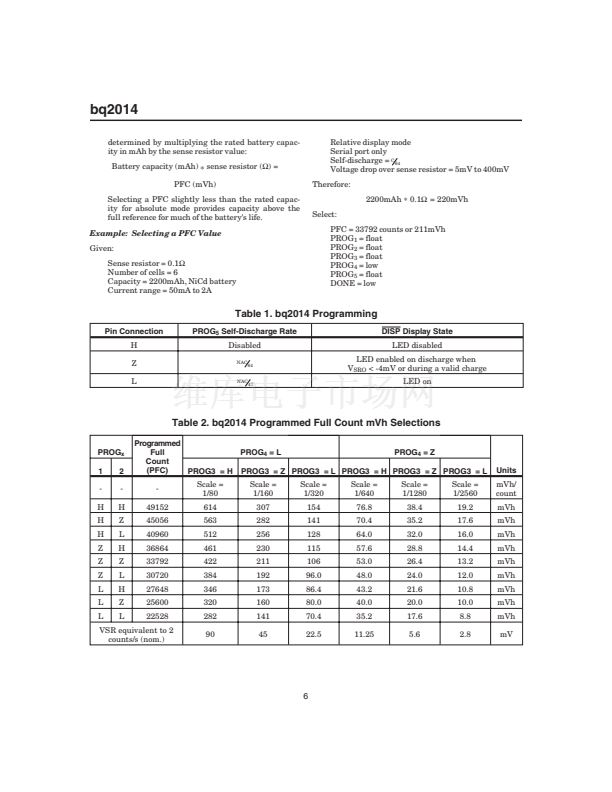
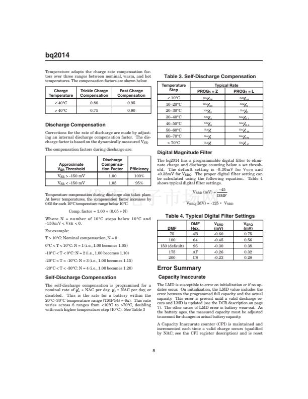
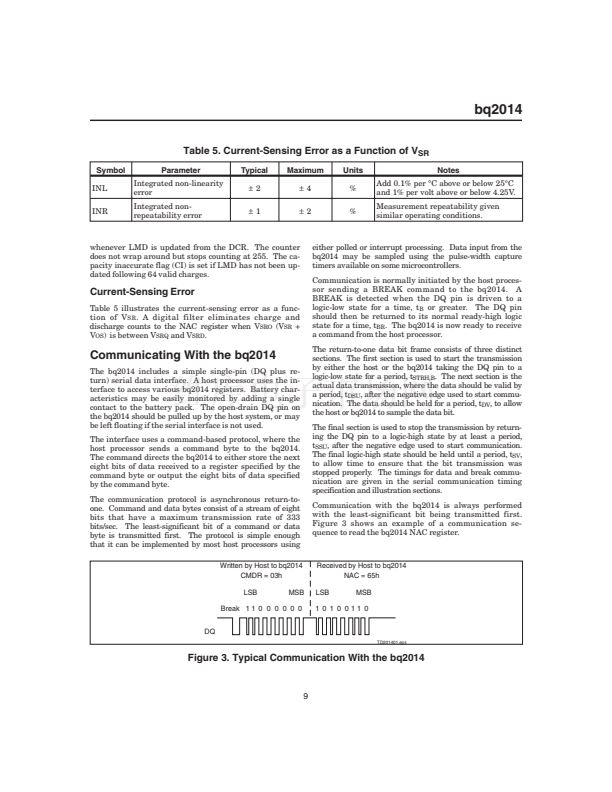
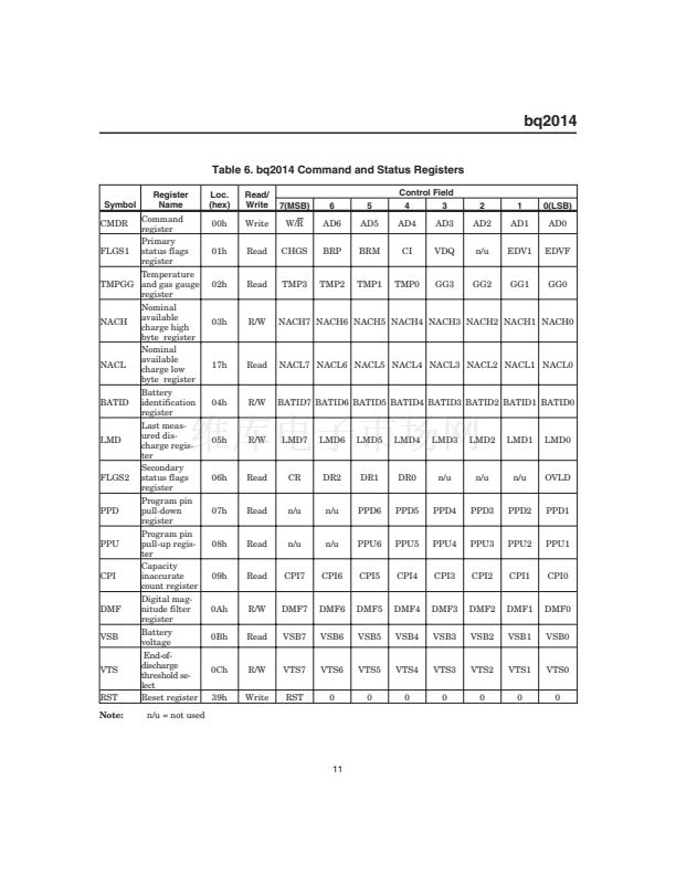
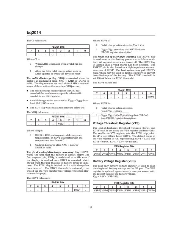
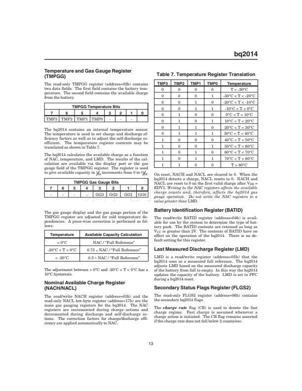
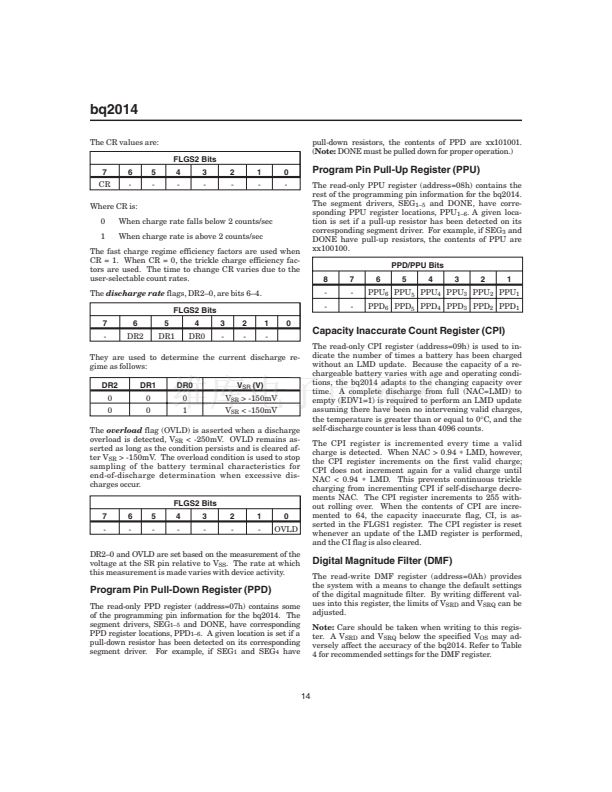
bq2014
Absolute Maximum Ratings
Symbol
V
CC
All other pins
REF
V
SR
Parameter
Relative to V
SS
Relative to V
SS
Relative to V
SS
Relative to V
SS
Minimum
-0.3
-0.3
-0.3
-0.3
0
Maximum
7.0
7.0
8.5
7.0
70
Unit
V
V
V
V
掳C
Current limited by R1 (see Figure 1)
Minimum 100鈩?series resistor should
be used to protect SR in case of a
shorted battery (see the bq2014 appli-
cation note for details).
Commercial
Notes
T
OPR
Note:
Operating tempera-
ture
Permanent device damage may occur if
Absolute Maximum Ratings
are exceeded. Functional opera-
tion should be limited to the Recommended DC Operating Conditions detailed in this data sheet. Expo-
sure to conditions beyond the operational limits for extended periods of time may affect device reliability.
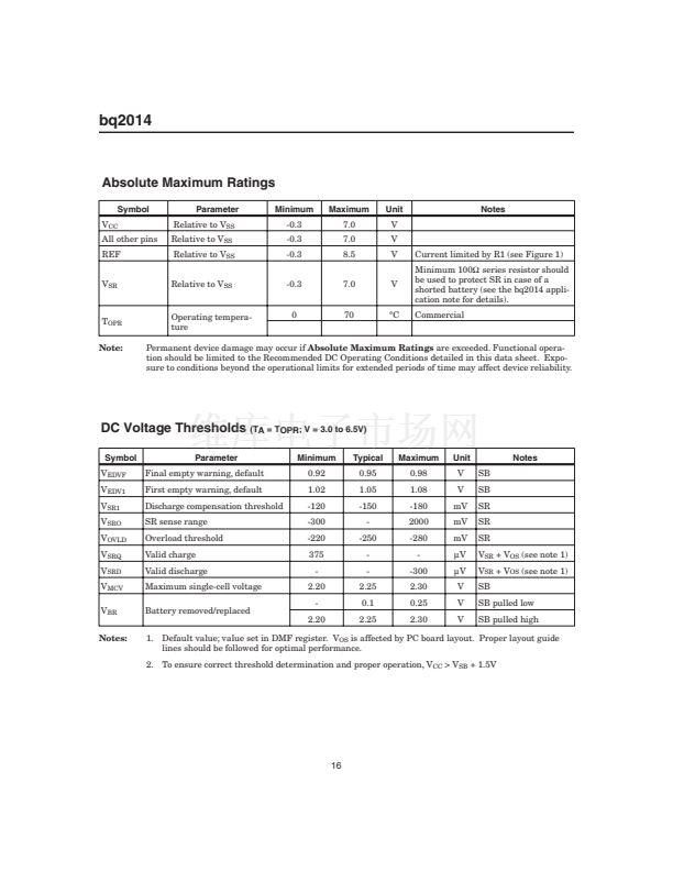
DC Voltage Thresholds
(TA = TOPR; V = 3.0 to 6.5V)
Symbol
V
EDVF
V
EDV1
V
SR1
V
SRO
V
OVLD
V
SRQ
V
SRD
V
MCV
V
BR
Notes:
Parameter
Final empty warning, default
First empty warning, default
Discharge compensation threshold
SR sense range
Overload threshold
Valid charge
Valid discharge
Maximum single-cell voltage
Battery removed/replaced
Minimum
0.92
1.02
-120
-300
-220
375
-
2.20
-
2.20
Typical
0.95
1.05
-150
-
-250
-
-
2.25
0.1
2.25
Maximum
0.98
1.08
-180
2000
-280
-
-300
2.30
0.25
2.30
Unit
V
V
mV
mV
mV
碌V
碌V
V
V
V
SB
SB
SR
SR
SR
V
SR
+ V
OS
(see note 1)
V
SR
+ V
OS
(see note 1)
SB
SB pulled low
SB pulled high
Notes
1. Default value; value set in DMF register. V
OS
is affected by PC board layout. Proper layout guide
lines should be followed for optimal performance.
2. To ensure correct threshold determination and proper operation, V
CC
> V
SB
+ 1.5V
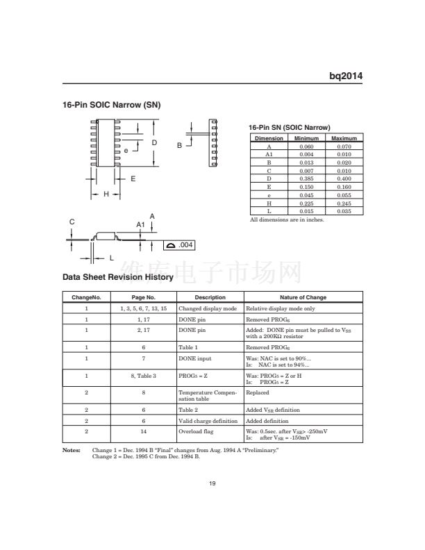
16


 1
1
 2
2
 3
3
 4
4
 5
5
 6
6
 7
7
 8
8
 9
9
 10
10
 11
11
 12
12
 13
13
 14
14
 15
15
 16
16
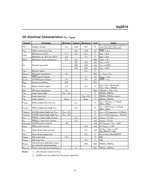 17
17
 18
18
 19
19
 20
20
 21
21
 22
22
