ISL95810
14. t
WC
is the minimum cycle time to be allowed for any non-volatile Write by the user, unless Acknowledge Polling is used. It is the time from a
valid STOP condition at the end of a Write sequence of a I
2
C serial interface Write operation, to the end of the self-timed internal non-volatile
write cycle.
15. V
IL
= 0V, V
IH
= V
CC
Typical Performance Curves
160
V
CC
= 2.7, T = 85掳C
140
WIPER RESISTANCE (鈩?
120
100
80
60
40
20
0
0
50
100
150
200
250
TAP POSITION (DECIMAL)
V
CC
= 5.5, T = -40掳C
V
CC
= 5.5, T = 85掳C
V
CC
= 5.5, T = 25掳C
STANDBY I
CC
(碌A)
V
CC
= 2.7, T = -40掳C
V
CC
= 2.7, T = 25掳C
1.8
1.6
1.4
1.2
1.0
0.8
0.6
0.4
0.2
0.0
2.7
3.2
25掳C
3.7
4.2
V
CC
(V)
4.7
5.2
85掳C
-40掳C
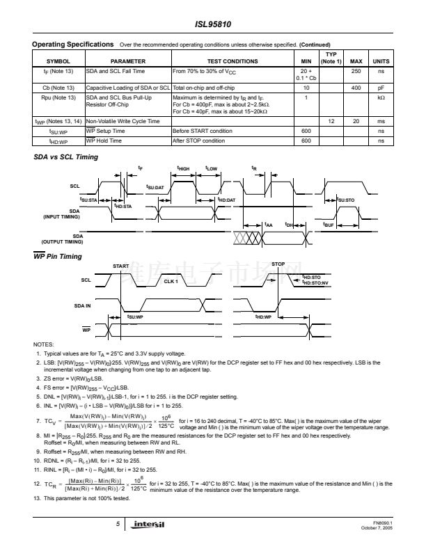
FIGURE 1. WIPER RESISTANCE vs TAP POSITION
[ I(RW) = V
CC
/ R
TOTAL
] for 50k鈩?(U)
FIGURE 2. STANDBY I
CC
vs V
CC
0.2
0.15
0.1
DNL (LSB)
0.3
V
CC
= 5.5, T = -40掳C
V
CC
= 2.7, T = 25掳C
V
CC
= 2.7, T = -40掳C
0.2
0.1
INL (LSB)
0
-0.1
V
CC
= 5.5, T = 25掳C
V
CC
= 2.7, T = 85掳C
V
CC
= 5.5, T = 85掳C
-0.2
-0.3
50
100
150
200
250
TAP POSITION (DECIMAL)
V
CC
= 2.7, T = -40掳C
V
CC
= 5.5, T = -40掳C
V
CC
= 5.5, T = 85掳C
0.05
0
-0.05
-0.1
-0.15
-0.2
0
V
CC
= 2.7, T = 25掳C
V
CC
= 2.7, T = 85掳C
V
CC
= 5.5, T = 25掳C
0
50
100
150
200
250
TAP POSITION (DECIMAL)
FIGURE 3. DNL vs TAP POSITION IN VOLTAGE DIVIDER
MODE FOR 10k鈩?(W)
FIGURE 4. INL vs TAP POSITION IN VOLTAGE DIVIDER
MODE FOR 10k鈩?(W)
6
FN8090.1
October 7, 2005


 1
1
 2
2
 3
3
 4
4
 5
5
 6
6
 7
7
 8
8
 9
9
 10
10
 11
11
 12
12
 13
13
