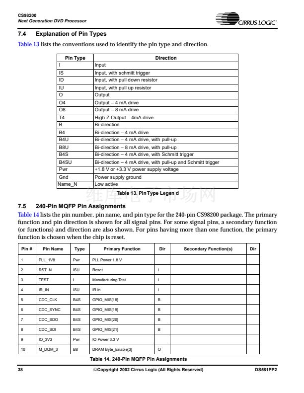
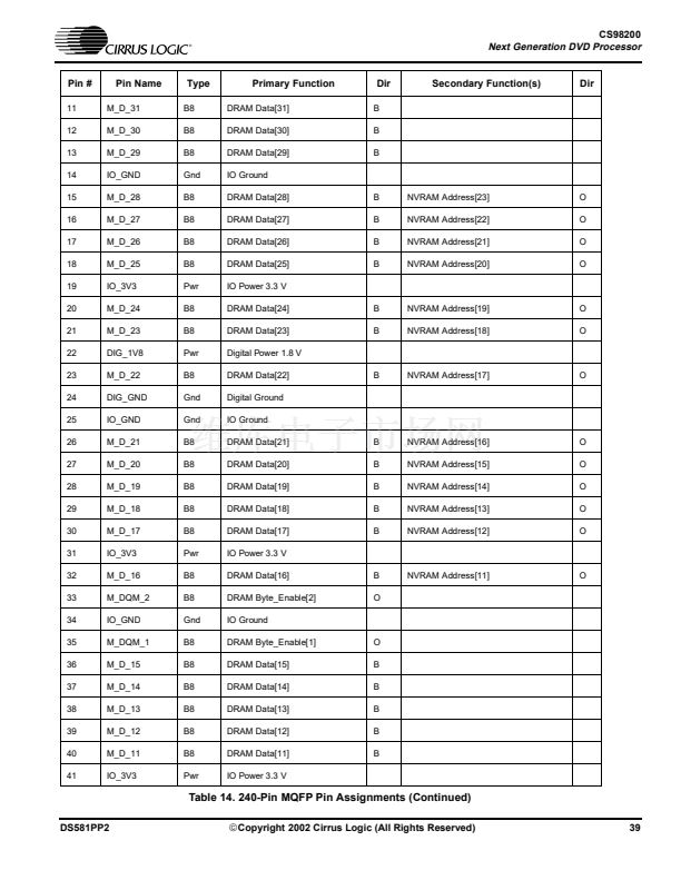
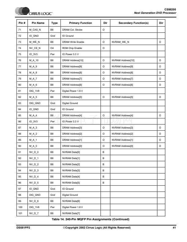
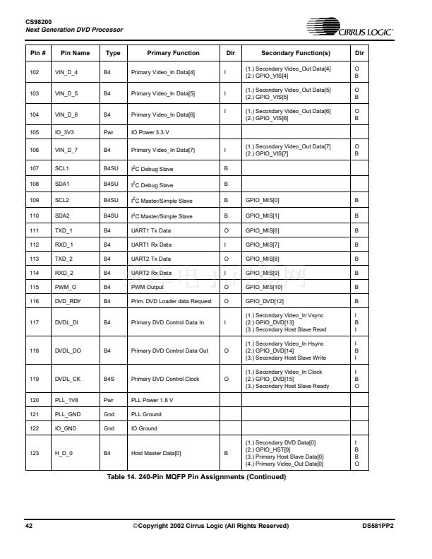
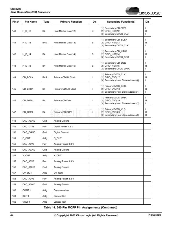
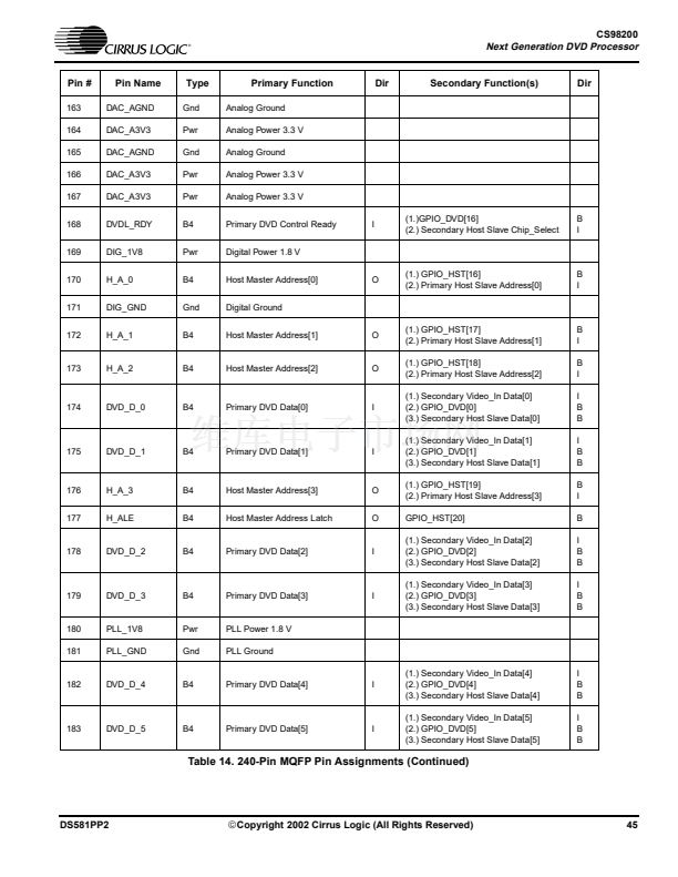
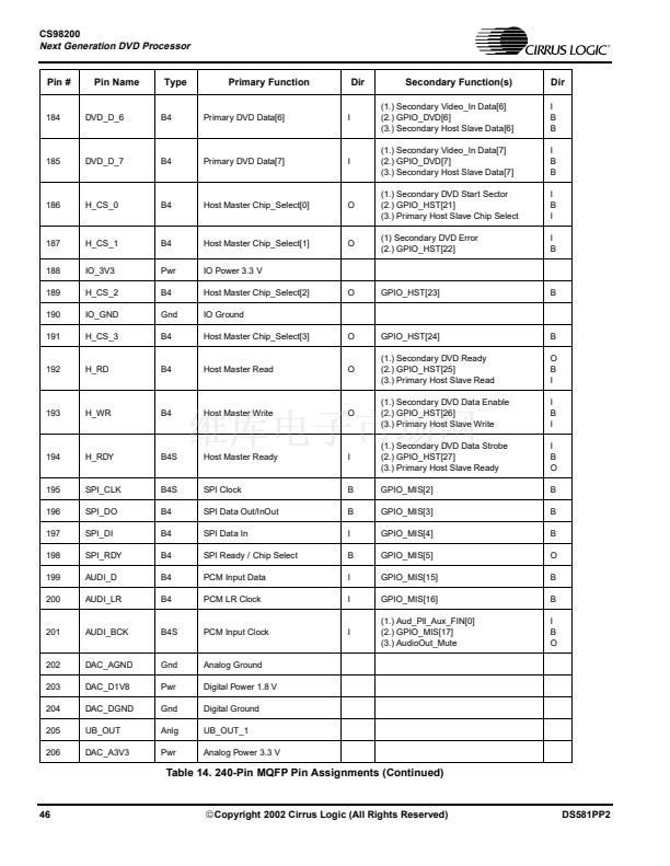
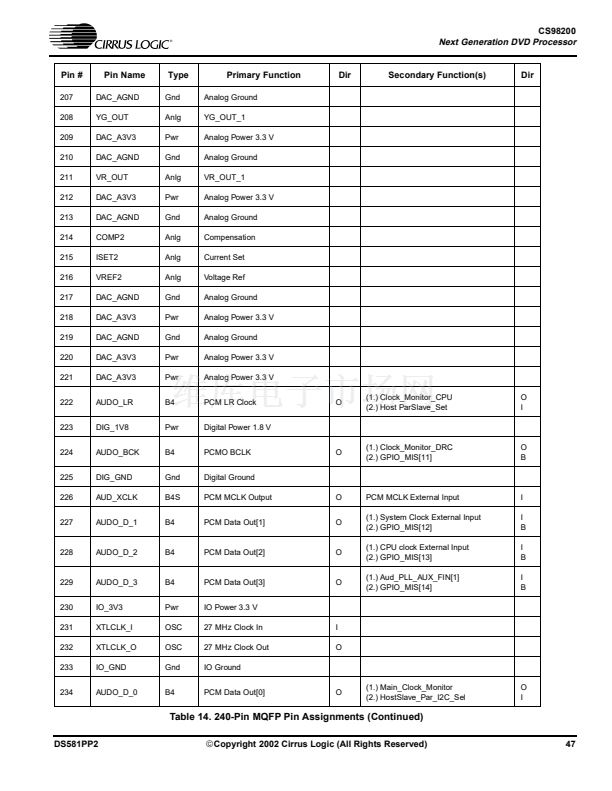
CS98200
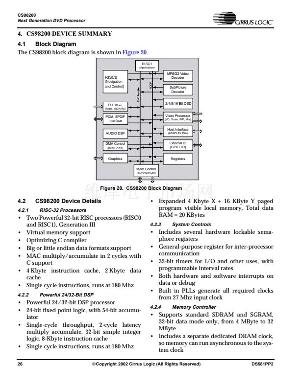
Next Generation DVD Processor
74
NV_CE_N
O
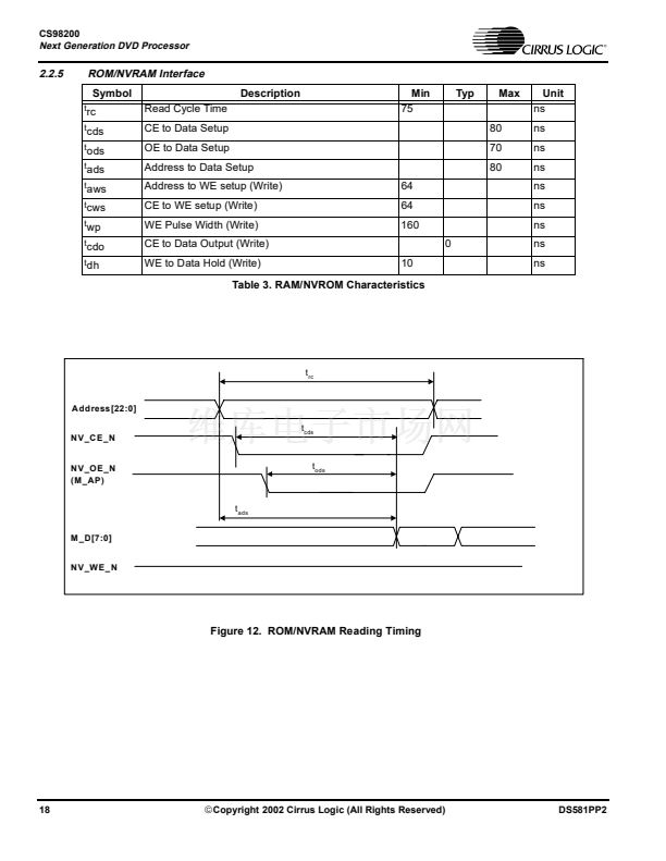
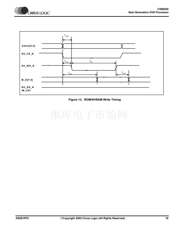
ROM/NVRAM Chip Enable.
Table 16. ROM/NVRAM Interface (Continued)
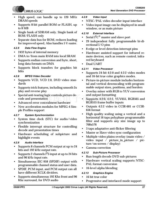
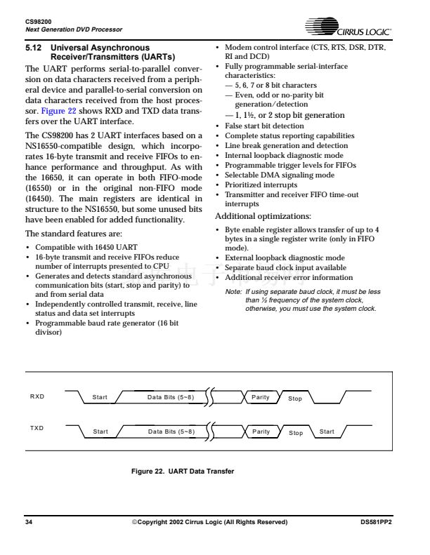
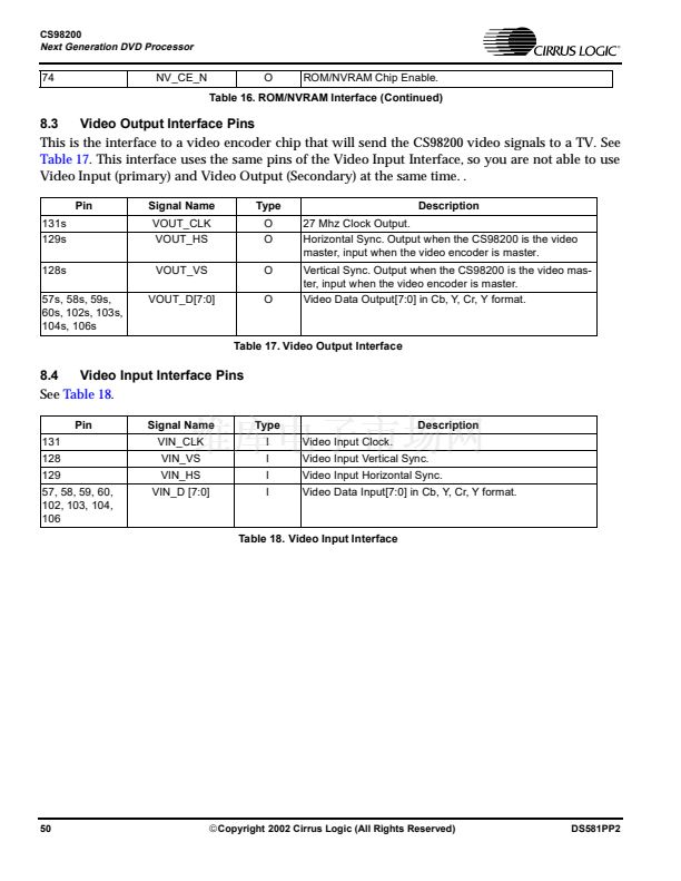
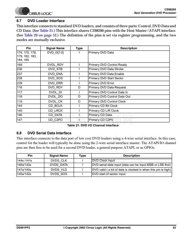
8.3
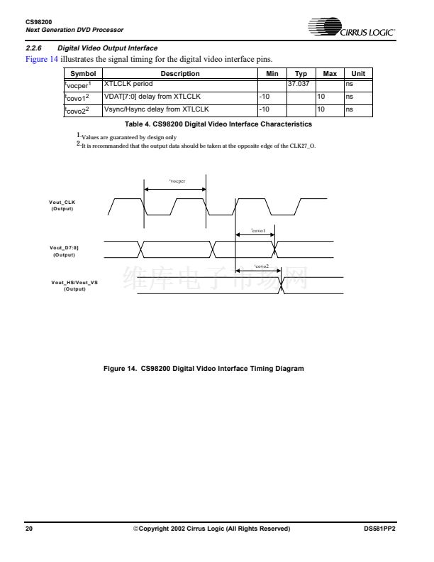
Video Output Interface Pins
This is the interface to a video encoder chip that will send the CS98200 video signals to a TV. See
Table 17.
This interface uses the same pins of the Video Input Interface, so you are not able to use
Video Input (primary) and Video Output (Secondary) at the same time. .
Pin
131s
129s
128s
57s, 58s, 59s,
60s, 102s, 103s,
104s, 106s
Signal Name
VOUT_CLK
VOUT_HS
VOUT_VS
VOUT_D[7:0]
Type
O
O
O
O
27 Mhz Clock Output.
Horizontal Sync. Output when the CS98200 is the video
master, input when the video encoder is master.
Vertical Sync. Output when the CS98200 is the video mas-
ter, input when the video encoder is master.
Video Data Output[7:0] in Cb, Y, Cr, Y format.
Description
Table 17. Video Output Interface
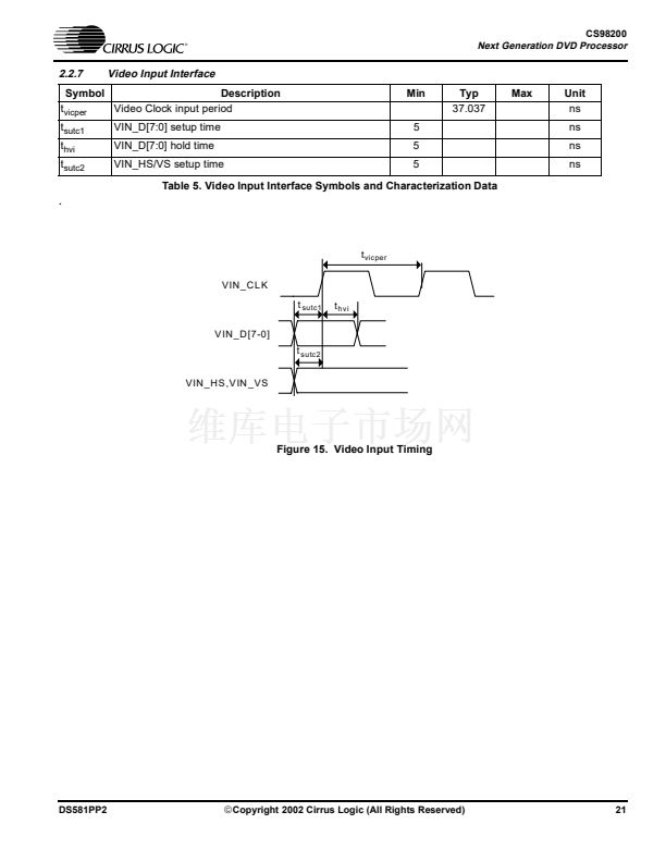
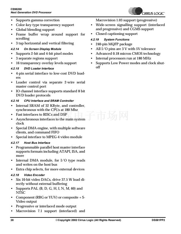
8.4
Video Input Interface Pins
See
Table 18.
Pin
131
128
129
57, 58, 59, 60,
102, 103, 104,
106
Signal Name
VIN_CLK
VIN_VS
VIN_HS
VIN_D [7:0]
Type
I
I
I
I
Video Input Clock.
Video Input Vertical Sync.
Video Input Horizontal Sync.
Video Data Input[7:0] in Cb, Y, Cr, Y format.
Description
Table 18. Video Input Interface
50
铮?/div>
Copyright 2002 Cirrus Logic (All Rights Reserved)
DS581PP2


 1
1
 2
2
 3
3
 4
4
 5
5
 6
6
 7
7
 8
8
 9
9
 10
10
 11
11
 12
12
 13
13
 14
14
 15
15
 16
16
 17
17
 18
18
 19
19
 20
20
 21
21
 22
22
 23
23
 24
24
 25
25
 26
26
 27
27
 28
28
 29
29
 30
30
 31
31
 32
32
 33
33
 34
34
 35
35
 36
36
 37
37
 38
38
 39
39
 40
40
 41
41
 42
42
 43
43
 44
44
 45
45
 46
46
 47
47
 48
48
 49
49
 50
50
 51
51
 52
52
 53
53
 54
54
 55
55
 56
56
 57
57
 58
58
 59
59
 60
60
