W TE
PO WE R SEM IC O ND UC TO R S
KBPC40, 50P/W SERIES
40, 50A HIGH CURRENT BRIDGE RECTIFIER
Features
!
!
!
!
!
!
Diffused Junction
Low Reverse Leakage Current
Low Power Loss, High Efficiency
Electrically Isolated Epoxy Case for
Maximum Heat Dissipation
Case to Terminal Isolation Voltage 2500V
UL Recognized File # E157705
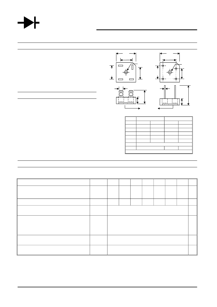
A
C
G
~
D
-
+
~
C
C
-
~
D
~
+
A
C
G
H
H
E
B
Metal Heat Sink
Mechanical Data
!
!
!
!
!
!
Case: Epoxy Case with Heat Sink Internally
Mounted in the Bridge Encapsulation
Terminals: Plated Leads Solderable per
MIL-STD-202, Method 208
Polarity: Symbols Marked on Case
Mounting: Through Hole for #10 Screw
Weight:
KBPC-P
24 grams (approx.)
KBPC-PW
21 grams (approx.)
Marking: Type Number
E
B
KBPC-PW
KBPC-P
"W鈥?Suffix Designates Wire Leads
No Suffix Designates Faston Terminals
*All Models are Available on B(Height)=7.9mm Max. Epoxy Case
Dim
A
B
C
D
E
G
H
KBPC-P
KBPC-PW
Min
Max
Min
Max
28.40
28.70
28.40
28.70
10.97
11.23
10.97
11.23
15.70
16.70
17.10
19.10
17.50
18.50
10.90
11.90
22.86
25.40
30.50
鈥?/div>
Hole for #10 screw, 5.08脴 Nominal
6.35 Typical
0.97脴
1.07脴
All Dimension in mm
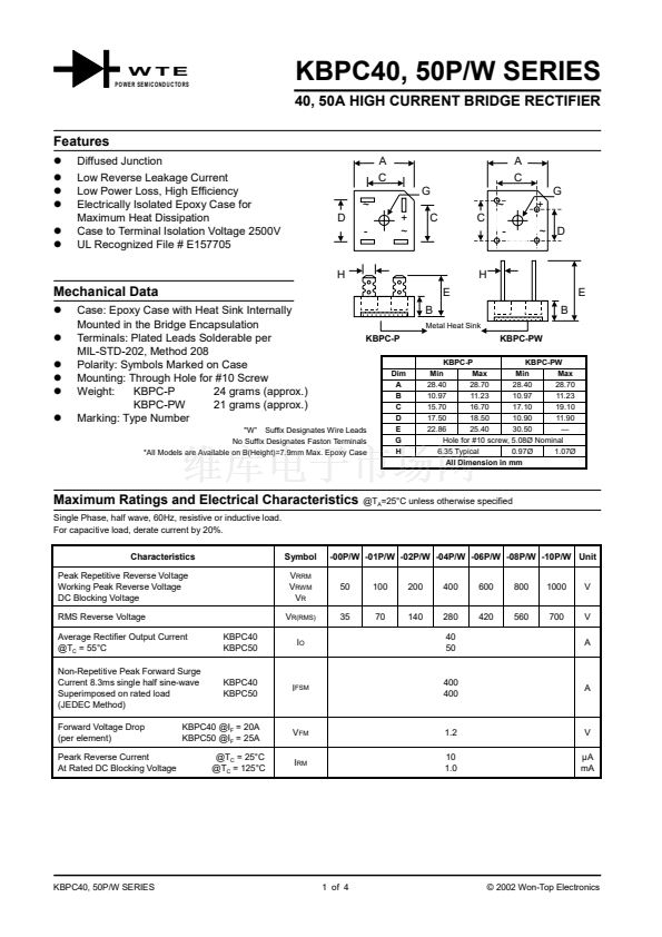
Maximum Ratings and Electrical Characteristics
Single Phase, half wave, 60Hz, resistive or inductive load.
For capacitive load, derate current by 20%.
Characteristics
Peak Repetitive Reverse Voltage
Working Peak Reverse Voltage
DC Blocking Voltage
RMS Reverse Voltage
Average Rectifier Output Current
@T
C
= 55掳C
Non-Repetitive Peak Forward Surge
Current 8.3ms single half sine-wave
Superimposed on rated load
(JEDEC Method)
Forward Voltage Drop
(per element)
Peark Reverse Current
At Rated DC Blocking Voltage
KBPC40
KBPC50
Symbol
V
RRM
V
RWM
V
R
V
R(RMS)
I
O
@T
A
=25掳C unless otherwise specified
-00P/W -01P/W -02P/W -04P/W -06P/W -08P/W -10P/W Unit
50
35
100
70
200
140
400
280
40
50
600
420
800
560
1000
700
V
V
A
KBPC40
KBPC50
I
FSM
400
400
A
KBPC40 @I
F
= 20A
KBPC50 @I
F
= 25A
@T
C
= 25掳C
@T
C
= 125掳C
V
FM
I
RM
1.2
10
1.0
V
碌A
mA
KBPC40, 50P/W SERIES
1 of 4
漏 2002 Won-Top Electronics


 1
1
 2
2
 3
3
 4
4
