DC COMPONENTS CO., LTD.
R
KBPC
MB
15005
1505
THRU
KBPC
1510
MB
1510
RECTIFIER SPECIALISTS
TECHNICAL SPECIFICATIONS OF
SINGLE-PHASE SILICON BRIDGE RECTIFIER
VOLTAGE RANGE - 50 to 1000 Volts
CURRENT - 15 Amperes
FEATURES
* Metal case for Maximum Heat Dissipation
* Surge overload ratings-300 Amperes
* Low forward voltage drop
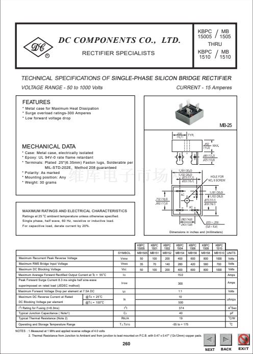
MB-25
MECHANICAL DATA
* Case: Metal case, electrically isolated
* Epoxy: UL 94V-0 rate flame retardant
* Terminals: Plated .25"(6.35mm) Faston lugs, Solderable per
MIL-STD-202E, Method 208 guaranteed
* Polarity: As marked
* Mounting position: Any
* Weight: 30 grams
MAXIMUM RATINGS AND ELECTRICAL CHARACTERISTICS
Ratings at 25
o
C ambient temperature unless otherwise specified.
Single phase, half wave, 60 Hz, resistive or inductive load.
For capacitive load, derate current by 20%.
Dimensions in inches and (millimeters)
KBPC
15005
SYMBOL
Maximum Recurrent Peak Reverse Voltage
Maximum RMS Bridge Input Voltage
Maximum DC Blocking Voltage
Maximum Average Forward Rectified Output Current at Tc = 55
o
C
Peak Forward Surge Current 8.3 ms single half sine-wave
superimposed on rated load (JEDEC method)
Maximum Forward Voltage Drop per element at 7.5A DC
Maximum DC Reverse Current at Rated
DC Blocking Voltage per element
I t Rating for Fusing (t<8.3ms)
Typical Junction Capacitance ( Note1)
Typical Thermal Resistance (Note 2)
Operating and Storage Temperature Range
NOTES : 1.Measured at 1 MH
Z
and applied reverse voltage of 4.0 volts
2
KBPC
1501
100
70
100
KBPC
1502
MB152
200
140
200
KBPC
1504
MB154
400
280
400
15.0
300
1.1
10
500
KBPC
1506
MB156
600
420
600
KBPC
1508
MB158
800
560
800
KBPC
1510
MB1510 UNITS
1000
700
1000
Volts
Volts
Volts
Amps
Amps
Volts
uAmps
A Sec
pF
0
MB1505 MB151
50
35
50
V
RRM
V
RMS
V
DC
I
O
I
FSM
V
F
o
o
@T
A
= 25 C
@T
C
= 100 C
I
R
I t
C
J
R胃J A
T
J,
T
STG
2
374
40
19
-55 to + 175
2
C/W
0
C
2. Thermal Resistance from Junction to Ambient and from junction to lead mounted on P.C.B. with 0.47 x 0.47" (12x12mm) copper pads.
260
NEXT
NEXT
NEXT
BACK
BACK
BACK
EXIT
EXIT
EXIT


 1
1
 2
2
