0,017鈩?/div>
卤50A
60W
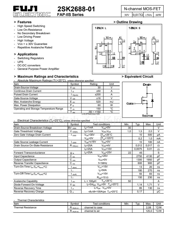
> Outline Drawing
> Applications
-
-
-
-
Switching Regulators
UPS
DC-DC converters
General Purpose Power Amplifier
> Maximum Ratings and Characteristics
- Absolute Maximum Ratings (T
C
=25掳C),
unless otherwise specified
Item
Drain-Source-Voltage
Continous Drain Current
Pulsed Drain Current
Gate-Source-Voltage
Max. Avalanche Energy
Max. Power Dissipation
Operating and Storage Temperature Range
Symbol
V
DS
I
D
I
D(puls)
V
GS
E
AV
P
D
T
ch
T
stg
Rating
30
卤50
卤200
卤16
520
60
150
-55 ~ +150
L=0.277mH,Vcc=12V
> Equivalent Circuit
Unit
V
A
A
V
mJ
W
掳C
掳C
- Electrical Characteristics (T
C
=25掳C),
unless otherwise specified
Item
Drain-Source Breakdown-Voltage
Gate Threshhold Voltage
Zero Gate Voltage Drain Current
Gate Source Leakage Current
Drain Source On-State Resistance
Forward Transconductance
Input Capacitance
Output Capacitance
Reverse Transfer Capacitance
Turn-On-Time t
on
(t
on
=t
d(on)
+t
r
)
Turn-Off-Time t
off
(t
on
=t
d(off)
+t
f
)
Avalanche Capability
Diode Forward On-Voltage
Reverse Recovery Time
Reverse Recovery Charge
- Thermal Characteristics
Item
Thermal Resistance
Symbol
BV
DSS
V
GS(th)
I
DSS
I
R
g
C
C
C
t
t
t
t
I
V
t
Q
GSS
DS(on)
fs
iss
oss
rss
d(on)
r
d(off)
f
AV
SD
rr
rr
Test conditions
I
D
=1mA
V
GS
=0V
I
D
=1mA
V
DS=
V
GS
V
DS
=30V
T
ch
=25掳C
V
GS
=0V
T
ch
=125掳C
V
GS
=卤16V
V
DS
=0V
I
D
=25A
V
GS
=4V
I
D
=25A
V
GS
=10V
I
D
=25A
V
DS
=25V
V
DS
=25V
V
GS
=0V
f=1MHz
V
CC
=15V
I
D
=50A
V
GS
=10V
R
GS
=10
鈩?/div>
T
ch
=25掳C
L = 100碌H
I
F
=2xI
DR
V
GS
=0V T
ch
=25掳C
I
F
=I
DR
V
GS
=0V
-dI
F
/dt=100A/碌s T
ch
=25掳C
Min.
30
1,0
Typ.
1,5
10
0,2
10
0,012
0,0075
45
2750
1300
600
13
180
55
150
1,14
85
0,17
Max.
2,0
500
1,0
100
0,017
0,01
4130
1950
900
20
270
83
230
1,71
130
22
50
Unit
V
V
碌A
mA
nA
鈩?/div>
鈩?/div>
S
pF
pF
pF
ns
ns
ns
ns
A
V
ns
碌C
Symbol
R
th(ch-c)
R
th(ch-a)
Test conditions
channel to case
channel to air
Min.
Typ.
Max.
2,08
125,0
Unit
掳C/W
掳C/W


 1
1
 2
2
 3
3
