HA5340/883
June 1994
High Speed, Low Distortion, Precision Monolithic
Sample and Hold Ampli铿乪r
Description
The HA-5340/883 combines the advantages of two sample/hold
architectures to create a new generation of monolithic sample/
hold. High amplitude, high frequency signals can be sampled
with very low distortion being introduced. The combination of
exceptionally fast acquisition time and speci铿乪d/characterized
hold mode distortion is an industry 铿乺st. Additionally, the AC
performance is only minimally affected by additional hold
capacitance.
To achieve this level of performance, the bene铿乼s of an
integrating output stage have been combined with the
advantages of a buffered hold capacitor. To the user this
translates to a front-end stage that has high bandwidth due to
charging only a small capacitive load and an output stage with
constant pedestal error which can be nulled out using the offset
adjust pins. Since the performance penalty for additional hold
capacitance is low, the designer can further minimize pedestal
error and droop rate without sacri铿乧ing speed.
Low distortion, fast acquisition, and low droop rate are the
result, making the HA-5340/883 the obvious choice for high
speed, high accuracy sampling systems.
Features
鈥?This Circuit is Processed in Accordance to MIL-STD-
883 and is Fully Conformant Under the Provisions of
Paragraph 1.2.1.
鈥?Fast Acquisition Time (0.01%) . . . . . . . . . . . . . . . 900ns
鈥?Fast Hold Mode Settling Time (0.01%) . . . . . . . . . 300ns
鈥?Low Distortion (Hold Mode) . . . . . . . . . . . -72dBc (Typ)
(V
IN
= 200kHz, Fs = 450kHz, 5V
P-P
)
鈥?Bandwidth Minimally Affected By External C
H
鈥?Fully Differential Analog Inputs
鈥?Built-in 135pF Hold Capacitor
鈥?Pin Compatible with HA-5320
Applications
鈥?High Bandwidth Precision Data Acquisition Systems
鈥?Inertial Navigation and Guidance Systems
鈥?Ultrasonics
鈥?SONAR
鈥?RADAR
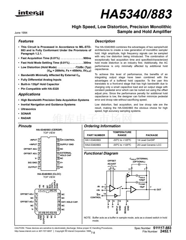
Pinouts
HA-5340/883 (CERDIP)
TOP VIEW
Ordering Information
PART NUMBER
TEMPERATURE
RANGE
-55
o
C to +125
o
C
-55
o
C to +125
o
C
PACKAGE
14 Lead CerDIP
20 Lead Ceramic LCC
-INPUT 1
+INPUT 2
OFFSET ADJ 3
OFFSET ADJ 4
V- 5
SIG GND 6
OUTPUT 7
14 S/H CONTROL
13 SUPPLY GND
12 NC
11 EXTERNAL
HOLD CAP
10 NC
9 V+
8 NC
HA1-5340/883
HA4-5340/883
Functional Diagram
OFFSET
ADJUST
3
4
C
HOLD
EXTERNAL
(OPTIONAL)
11
7
HA-5340/883 (CLCC)
TOP VIEW
NC
S/H
CNTL
SUPPLY
GND
1
2
14
9
+V
5
-V
13
SUPPLY
GND
6
*
C
HOLD
120pF
-IN
+IN
C
COMP
15pF
7
OUT
+IN
3
OFFSET ADJ
NC
OFFSET ADJ
NC
4
5
6
7
-IN
2
1 20 19
18 NC
17 NC
16 EXT. HOLD CAP.
15 NC
14 NC
S/H
CONTROL
V- 8
9 10 11 12 13
SIG
GND
OUTPUT
NC
NC
V+
NOTE: Buffer acts as a buffer in sample mode, acts as a closed switch in hold
mode.
SIGNAL
GND
CAUTION: These devices are sensitive to electrostatic discharge; follow proper IC Handling Procedures.
http://www.intersil.com or 407-727-9207
|
Copyright
漏
Intersil Corporation 1999
7-8
Spec Number
511117-883
File Number
2452.1


 1
1
 2
2
 3
3
 4
4
 5
5
 6
6
 7
7
 8
8
 9
9
 10
10
 11
11
 12
12
